Intel SR1530CL User Guide
Intel SR1530CL - Server System - 0 MB RAM Manual
 |
UPC - 735858189880
View all Intel SR1530CL manuals
Add to My Manuals
Save this manual to your list of manuals |
Intel SR1530CL manual content summary:
- Intel SR1530CL | User Guide - Page 1
Intel® Server System SR1530CL / SR1530HCL / SR1530HCLS and Intel® Server System SR1530CLR / SR1530HCLR / SR1530HCLSR User Guide A Guide for Technically Qualified Assemblers of Intel® Identified Subassemblies/Products Intel Order Number D68456-005 - Intel SR1530CL | User Guide - Page 2
Pentium, and Intel Xeon are trademarks or registered trademarks of Intel Corporation or its subsidiaries in the United States and other countries. * Other names and brands may be claimed as the property of others. Copyright © 2010, Intel Corporation. All Rights Reserved ii Server System User Guide - Intel SR1530CL | User Guide - Page 3
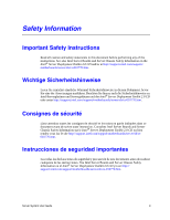
y precaución de este documento antes de realizar cualquiera de las instrucciones. Vea Intel Server Boards and Server Chassis Safety Information en el Intel® Server Deployment Toolkit 2.0 CD y/o en http:// support.intel.com/support/motherboards/server/sb/cs-010770.htm. Server System User Guide iii - Intel SR1530CL | User Guide - Page 4
http://support.intel.com/support/motherboards/server/sb/CS-010770.htm 上的 Intel Server Boards and Server Chassis Safety Information(《Intel iv Server System User Guide - Intel SR1530CL | User Guide - Page 5
wide sides can damage the contacts inside the jumper, causing intermittent problems with the function controlled by that jumper. Take care to grip with, but not squeeze, the pliers or other tool you use to remove a jumper, or you may bend or break the pins on the board. Server System User Guide v - Intel SR1530CL | User Guide - Page 6
vi Server System User Guide - Intel SR1530CL | User Guide - Page 7
technical specifications, troubleshooting information, complete safety information, regulatory information, "getting help" information, and the warranty. Product Contents The Intel® Server System SR1530CL / SR1530HCL / SR1530HCLS ships with the Intel® Server Board S5000VCL. Server System User Guide - Intel SR1530CL | User Guide - Page 8
. Intel® Server System Contents Your Intel® Server System SR1530CL / SR1530HCL / SR1530HCLS and/or the Intel® Server System SR1530CLR / SR1530HCLR / SR1530HCLSR ships with the following items: • One Intel® Server Board S5000VCL/S5000VCLR, installed in the server system • One 400-watt power supply - Intel SR1530CL | User Guide - Page 9
.intel.com/support/motherboards/server/ S5000VCL/ Intel® Server Board S5000VCL Technical Product Specification Found at: http://support.intel.com/support/motherboards/server/ S5000VCL/ Intel® Server System SR1530CL / SR1530HCL / SR1530HCLS Quick Start User's Guide Intel® Server System SR1530CLR - Intel SR1530CL | User Guide - Page 10
Systems List Found at: http://support.intel.com/support/motherboards/server/ S5000VCL/ Intel® System Management Found at: http://support.intel.com/support/motherboards/server/ S5000VCL/ Diagnostics Found at: http://support.intel.com/support/motherboards/server/ S5000VCL/ x Server System User Guide - Intel SR1530CL | User Guide - Page 11
this Manual ...vii Manual Organization ...vii Product Contents ...vii Intel® Server System Contents viii Server System References ix Chapter 1: Server System Features 1 Chassis Component Identification 4 Front Control Panel (SR1530CL/SR1530CLR 4 Front Control Panel (SR1530HCL/SR1530HCLS and - Intel SR1530CL | User Guide - Page 12
Processor 41 Installing and Removing a Hard Drive (SR1530CL/SR1530CLR 42 Installing a Hard Disk Drive (SR1530CL/SR1530CLR 42 Removing a Hard Disk Drive (SR1530CL/SR1530CLR 46 Installing and Removing a Hot-Swap SAS/SATA Drive (SR1530HCL/SR1530HCLS PCI Add-in Card 68 xii Server System User Guide - Intel SR1530CL | User Guide - Page 13
Data Cable Routing (SR1530CL/SR1530CLR 100 Data Cable Routing (SR1530HCL/SR1530HCLS and SR1530HCLR/SR1530HCLSR) . 101 400-W Single Power Supply Input Voltages 102 400-W Single Power Supply Output Voltages 102 System Environmental Specifications 103 Appendix B: Troubleshooting 105 Resetting the - Intel SR1530CL | User Guide - Page 14
Server Safety Information 121 Safety Warnings and Cautions 121 Intended Application Uses 122 Site Selection ...122 Equipment Handling Practices 122 Power and Electrical Warnings 123 System quipement 133 Alimentation et avertissements en matiére d'électricit 133 xiv Server System User Guide - Intel SR1530CL | User Guide - Page 15
ática (ESD 142 Otros riesgos ...143 Appendix E: Installation / Assembly Safety Instructions 145 English ...145 Deutsch ...147 Français ...149 Español ...151 Product Recycling 168 Appendix G: Warranty 169 Limited Warranty for Intel® Chassis Subassembly Products 169 Server System User Guide xv - Intel SR1530CL | User Guide - Page 16
xvi Server System User Guide - Intel SR1530CL | User Guide - Page 17
1. Intel® Server System SR1530CL / SR1530HCL / SR1530HCLS and Intel Server System SR1530CLR / SR1530HCLR / SR1530HCLSR Feature Summary 2 Table 2. NIC LED Descriptions 6 Table 3. Setup Menu Key Use 18 Table 4. Power Supply Output Capability 102 Table 5. System Environmental Specifications 103 - Intel SR1530CL | User Guide - Page 18
xviii Server System User Guide - Intel SR1530CL | User Guide - Page 19
Duct (SR1530HCL/SR1530HCLS and SR1530HCLR/ SR1530HCLSR)...34 Figure 28. Installing the Memory 36 Figure 29. Lifting the Processor Socket Handle 38 Figure 30. Opening the Load Plate 38 Figure 31. Removing the Shipping Cover 39 Figure 32. Installing the Processor 39 Server System User Guide xix - Intel SR1530CL | User Guide - Page 20
Hard Drive Power and Data Cables (SR1530CL/SR1530CLR) ......... 45 Figure 40. Removing Drive Carrier from the Server System (SR1530CL/SR1530CLR) ........ 46 Figure 41. Install Drive Assemby into the Server System (SR1530CL/SR1530CLR 47 Figure 42. Locating Drive Positions (SR1530HCL/SR1530HCLS and - Intel SR1530CL | User Guide - Page 21
Power Cable Routing (SR1530CL/SR1530CLR 98 Figure 98. Power Cable Routing (SR1530HCL/SR1530HCLS and SR1530HCLR/ SR1530HCLSR)...99 Figure 99. Data Cable Routing (SR1530CL/SR1530CLR 100 Figure 100. Data Cable Routing (SR1530HCL/SR1530HCLS and SR1530HCLR/ SR1530HCLSR)...101 Server System User Guide - Intel SR1530CL | User Guide - Page 22
xxii Server System User Guide - Intel SR1530CL | User Guide - Page 23
, a list of the server system features, and diagrams showing the location of important components and connections on the server system. Figure 1. Intel® Server System SR1530CL/SR1530CLR Figure 2. Intel® Server System SR1530HCL / SR1530HCLS and SR1530HCLR / SR1530HCLSR Server System User Guide 1 - Intel SR1530CL | User Guide - Page 24
system. Table 1. Intel® Server System SR1530CL / SR1530HCL / SR1530HCLS and Intel Server System SR1530CLR / SR1530HCLR / SR1530HCLSR Feature Summary Feature Description Dimensions (SR1530CL/ SR1530CLR) Dimensions (SR1530HCL/ SR1530HCLS and SR1530HCLR/ SR1530HCLSR) Server Board Processor Memory - Intel SR1530CL | User Guide - Page 25
1. Intel® Server System SR1530CL / SR1530HCL / SR1530HCLS and Intel Server System SR1530CLR / SR1530HCLR / SR1530HCLSR Feature Summary Feature Expansion Capabilities Hard Drives Peripherals Front control panel LEDs and buttons Power Supply Fans USB System Management Description • Supports one - Intel SR1530CL | User Guide - Page 26
the chassis cover to assist in identifying components. Front Control Panel (SR1530CL/SR1530CLR) The front control panel of the Intel® Server System SR1530CL/SR1530CLR includes the following buttons and LEDs. A B CD F EG AF001182 A. USB Port B. Power Button C. System Status LED D. System Power LED - Intel SR1530CL | User Guide - Page 27
the following buttons and LEDs. B E ACD GF AF001610 A. NIC1 LED B. NIC2 LED C. System Power LED D. System Status LED E. Hard Disk Drive Activity LED F. USB Port G. Power Button Figure 4. Front Controls and LEDs (SR1530HCL/SR1530HCLS and SR1530HCLR/SR1530HCLSR) Server System User Guide 5 - Intel SR1530CL | User Guide - Page 28
System Rear A B C D F I E GH J AF001183 A. AC Power Connector B. Mouse Socket C. PCI Express* Slot D. Full-height PCI-X Slot E. Keyboard Socket F. USB 0-1 G. Serial Port A H. Video I. NIC (if left LED is on or blinking) 100 Mbps connection 1000 Mbps connection 6 Server System User Guide - Intel SR1530CL | User Guide - Page 29
Peripheral Devices The server system provides locations and hardware for installing hard drives, CD-ROM drive, or DVD-ROM Disk Drive Bay HDD0 (located under the slimline optical drive bay) C. Hard Disk Drive Bay HDD1 Figure 6. Optional Peripherals (SR1530CL/SR1530CLR) Server System User Guide 7 - Intel SR1530CL | User Guide - Page 30
A B AF001611 A. Slimline Optical Drive Bay (CD/DVD) B. Hard Disk Drive Bay (3) Figure 7. Optional Peripherals (SR1530HCL/SR1530HCLS and SR1530HCLR/SR1530HCLSR) 8 Server System User Guide - Intel SR1530CL | User Guide - Page 31
Drives can consume up to 17 watts of power each. Drives must be specified to run at a maximum ambient temperature of 45o C. Note: The Intel® Server System SR1530CL / SR1530HCL / SR1530HCLS and the Intel® Server System SR1530CLR / SR1530HCLR / SR1530HCLSR do not support all SAS/SATA hard drives. See - Intel SR1530CL | User Guide - Page 32
Processor Air Duct D. PCI Add-in Card Bracket E. System Memory DIMM Sockets F. Power Supply G. Processor Sockets (two) H. System Blowers (two) I. Hard Drive Brackets (two) J. Control Panel K. Slimline Optical Drive Bay Figure 8. Chassis Components (SR1530CL/SR1530CLR) 10 Server System User Guide - Intel SR1530CL | User Guide - Page 33
C. PCI Cooling Baffle D. System Blowers (2) E. Processor Air Duct F. PCI Add-in Card Bracket G. Server Board H. Power Supply I. Control Panel Board J. Control Panel K. Hard Disk Drives (3) Figure 9. Chassis Components (SR1530HCL/SR1530HCLS and SR1530HCLR/SR1530HCLSR) Server System User Guide 11 - Intel SR1530CL | User Guide - Page 34
T. SATA 2 (SAS 0 in SR1530HCLS/ SR1530HCLSR) U. SATA 3 (SAS 1 in SR1530HCLS/ SR1530HCLSR) V. SATA 4 (SAS 2 in SR1530HCLS/ SR1530HCLSR) W. SATA 5 (SAS 3 in SR1530HCLS/ SR1530HCLSR) X. CMOS Battery Y. SGPIO SAS Figure 10. Server Board Connector and Component Locations 12 Server System User Guide - Intel SR1530CL | User Guide - Page 35
will be cleared on the next server reset. These pins should not be jumpered for normal operation. Disable Force Update: These pins should be jumpered for normal operation. Enable Force Update: Jumpering these pins forces a BMC update. Figure 11. Configuration Jumpers Server System User Guide 13 - Intel SR1530CL | User Guide - Page 36
Board S5000VCL Technical Product Specification. For information on setting up RAID, see the RAID Software Guide that is included on the Intel® Server Deployment Toolkit 2.0 CD. Rack-Mounted Systems The Intel® Server System SR1530CL / SR1530HCL / SR1530HCLS and the Intel® Server System SR1530CLR - Intel SR1530CL | User Guide - Page 37
supported processors, see http:// support.intel.com/support/motherboards/s5000vsl/sb/CS-023399.htm. Memory The Intel® Server System SR1530CL / SR1530HCL / SR1530HCLS and the Intel® Server System SR1530CLR B1 DIMM B2 DIMM B3 Server System User Guide AF001076 Figure 12. Identifying DIMM Sockets 15 - Intel SR1530CL | User Guide - Page 38
only FBDIMM 667-MHz fully buffered, registered DIMM modules. - Use only FBDIMMs that comply with the JEDEC Revision 2.0 specifications. - Use only 240-pin DIMMs. For a complete list of supported memory DIMMs, see the links under "Server System References" on page ix. 16 Server System User Guide - Intel SR1530CL | User Guide - Page 39
system being present. See "Server System References" on page ix for a link to the Intel® 5000 Series Chipsets Server Board Family Datasheet where you will find details about specific BIOS Setup, you might need to clear the CMOS memory. For instructions on clearing the CMOS, see ""Clearing the CMOS" - Intel SR1530CL | User Guide - Page 40
in any major menu, the exit confirmation window is displayed and the user is asked whether changes can be discarded. Setup Defaults - Pressing - Intel SR1530CL | User Guide - Page 41
the BIOS in flash memory. The code and data in the upgrade file include the following: • On-board system BIOS, including the may need to be followed to return the system to service. See "Server System References" on page ix for a link server at the end of the procedure. Server System User Guide 19 - Intel SR1530CL | User Guide - Page 42
update process is completed. Note: You may encounter a CMOS Checksum error or other problem after reboot. If this happens, shut down the system and boot it again. CMOS checksum errors require that you enter Setup, check your settings, save your settings, and exit Setup. 20 Server System User Guide - Intel SR1530CL | User Guide - Page 43
the AC power. 5. Power up the system. 6. Power down the system and disconnect the AC power. 7. Return the Password Clear jumper to the Password Clear Protect position, covering pins 1 and 2. 8. Close the server chassis. 9. Reconnect the AC power and power up the server. Server System User Guide 21 - Intel SR1530CL | User Guide - Page 44
AC power 5. Power up the system. 6. When the system begins beeping, power it down and disconnect the AC power. 7. Return the jumper to the Normal Operation location, covering pins 1 and 2. 8. Close the server chassis. 9. Reconnect the AC power and power up the system. 22 Server System User Guide - Intel SR1530CL | User Guide - Page 45
the AC power 5. Power up the system. 6. When the system begins beeping, power it down and disconnect the AC power. 7. Return the jumper to the Disabled location, covering pins 1 and 2. 8. Close the server chassis. 9. Reconnect the AC power and power up the system. Server System User Guide 23 - Intel SR1530CL | User Guide - Page 46
24 Server System User Guide - Intel SR1530CL | User Guide - Page 47
in this chaper show the Intel® Server System SR1530CL / SR1530CLR with an optional optical drive installed. The instructions for removing and installing components are the same for the Intel® Server System SR1530HCL / SR1530HCLS and the ntel® Server System SR1530HCLR / SR1530HCLSR unless otherwise - Intel SR1530CL | User Guide - Page 48
Removing the Front Bezel Use the steps below if your system includes a front bezel. 1. Unlock the bezel. 2. Disconnect any cables attached to the control panel. 3. Pull the bezel from the server system. AF001057 Figure 16. Removing the Front Bezel (SR1530CL/SR1530CLR) 26 Server System User Guide - Intel SR1530CL | User Guide - Page 49
end of the bezel, line up the center notch on the bezel with the center guide on the rack handles. 2. Push the bezel onto the front of the server system until it clicks into place. 3. Lock the bezel. AF001056 Figure 18. Installing the Front Bezel (SR1530CL/SR1530CLR) Server System User Guide 27 - Intel SR1530CL | User Guide - Page 50
"Safety Information" on page iii. 2. Turn off all peripheral devices connected to the server. Turn off the server. 3. Disconnect the AC power cord. 4. (SR1530CL/SR1530CLR) Remove the two screws at the front of the chassis (see letter "A" in the following figure). Loosen the screw at the rear of the - Intel SR1530CL | User Guide - Page 51
B C A AF000971 Figure 20. Removing the Server System Cover (SR1530CL/SR1530CLR) Server System User Guide 29 - Intel SR1530CL | User Guide - Page 52
Removing the Server System Cover (SR1530HCL/SR1530HCLS and SR1530HCLR/SR1530HCLSR) Installing the Server System Cover 1. Observe the safety and ESD precautions at the beginning of this book. See "Safety Information" on page iii. 2. (SR1530CL/SR1530CLR) Place the cover over the server system so that - Intel SR1530CL | User Guide - Page 53
B A C AF000972 Figure 22. Installing the Server System Cover (SR1530CL/SR1530CLR) 3. (SR1530HCL/SR1530HCLS and SR1530HCLR/SR1530HCLSR) Place the cover over the server system so that the side edges of the cover sit just inside the server system sidewalls. Slide the cover forward (see letter "A" in - Intel SR1530CL | User Guide - Page 54
fans. See Figure 24 for the Intel® Server System SR1530CL / SR1530CLR. See Figure 25 for the Intel® Server System SR1530HCL / SR1530HCLS and the Intel® Server System SR1530HCLR / SR1530HCLSR. AF000973 Figure 24. Removing the Processor Air Duct (SR1530CL/SR1530CLR) 32 Server System User Guide - Intel SR1530CL | User Guide - Page 55
Use caution not to pinch or disengage cables that may be near or under the air duct. See Figure 26 for the Intel® Server System SR1530CL / SR1530CLR. See Figure 27 for the Intel® Server System SR1530HCL / SR1530HCLS and the Intel® Server System SR1530HCLR / SR1530HCLSR. Server System User Guide 33 - Intel SR1530CL | User Guide - Page 56
AF000974 Figure 26. Installing the Processor Air Duct (SR1530CL/SR1530CLR) AF001618 Figure 27. Installing the Processor Air Duct (SR1530HCL/SR1530HCLS and SR1530HCLR/SR1530HCLSR) 34 Server System User Guide - Intel SR1530CL | User Guide - Page 57
. See "Safety Information" on page iii. 2. Power down the server and unplug all peripheral devices and the AC power cable. 3. Remove the server system cover. For instructions, see "Removing the Server System Cover" on page 28. 4. Locate the DIMM sockets. See Figure 28. Server System User Guide 35 - Intel SR1530CL | User Guide - Page 58
Socket DIMM B2 Socket DIMM B3 Socket D A C B Figure 28. Installing the Memory AF000648 5. Make sure the clips at both ends of the DIMM socket(s) are pushed . 11. Install the server system cover. For instructions, see "Installing the Server System Cover" on page 30. 36 Server System User Guide - Intel SR1530CL | User Guide - Page 59
on page iii. 2. Power down the server and unplug all peripheral devices and the AC power cable. 3. Remove the server system cover. For instructions, see "Removing the Server System Cover" on page 28. 4. Locate the processor socket and raise the socket handle completely. Server System User Guide 37 - Intel SR1530CL | User Guide - Page 60
AF000650 Figure 29. Lifting the Processor Socket Handle 5. Push the rear tab with your finger to slightly lift the front of the load plate. Raise Figure 30. Opening the Load Plate Caution: Do not touch the socket pins; they are very sensitive and easily damaged. 38 Server System User Guide - Intel SR1530CL | User Guide - Page 61
alignment triangle mark and the alignment triangle cutout align correctly. A B AF000654 Figure 32. Installing the Processor 8. Remove the protective socket cover. Note: Retain the protective socket cover for use when removing a processor that will not be replaced. Server System User Guide 39 - Intel SR1530CL | User Guide - Page 62
system. 2. Set the heat sink over the processor, lining up the four captive screws with the four posts surrounding the processor. Install the heat sinks with the corner tabs pointed away from the power supply screw in the same order until each screw is firmly tightened. 40 Server System User Guide - Intel SR1530CL | User Guide - Page 63
and Processor 1. Observe the safety and ESD precautions at the beginning of this book. See "Safety Information" on page iii. 2. Power down the server and unplug all peripheral devices and the AC power cable. 3. Remove the server system cover. For instructions, see "Removing the Server System Cover - Intel SR1530CL | User Guide - Page 64
drives. See "Server System References" on page ix" for an Internet link to a list of supported hardware. Installing a Hard Disk Drive (SR1530CL/SR1530CLR) Note: If you are replacing a hard disk drive, see "Removing a Hard Disk Drive (SR1530CL/ SR1530CLR)" on page 46 for instructions first. Return - Intel SR1530CL | User Guide - Page 65
will use it later to reinstall the drive assembly. Lift the drive carrier from the chassis (see letter "B"). A B ChFarsosnist AF001050 Figure 36. Removing Drive Carrier from Server System (SR1530CL/ SR1530CLR) 7. Position the drive with the drive connectors facing up, as shown in the following - Intel SR1530CL | User Guide - Page 66
SR1530CL/SR1530CLR) 8. Set the drive assembly into place in the chassis. See letter "A" in the following figure. 9. Attach the drive assembly to the chassis the system. C A HDD 0 HDD 1 AF000976 Figure 38. Install Drive Assemby into Server System (SR1530CL/ SR1530CLR) 44 Server System User Guide - Intel SR1530CL | User Guide - Page 67
installed in the HDD0 carrier, attach the middle connector on the daisy chain power cable to the HDD0 power connector. See letter "C" in Figure 39. B A1 0 HDD 0 C A B D HDD 1 AF001178 Figure 39. Connecting Hard Drive Power and Data Cables (SR1530CL/ SR1530CLR) Server System User Guide 45 - Intel SR1530CL | User Guide - Page 68
Install the server system cover. For instructions, see "Installing the Server System Cover" on page 30. Removing a Hard Disk Drive (SR1530CL/SR1530CLR) 1. Observe the safety and ESD precautions at the beginning of this book. See "Safety Information" on page iii. 2. Power down the server and unplug - Intel SR1530CL | User Guide - Page 69
Figure 41. Install Drive Assemby into the Server System (SR1530CL/ SR1530CLR) 11. Install the server system cover. For instructions, see "Installing the Server System Cover" on page 30. Installing and Removing a Hot-Swap SAS/SATA Drive (SR1530HCL/SR1530HCLS and SR1530HCLR/SR1530HCLSR) Up to three - Intel SR1530CL | User Guide - Page 70
Drive Positions (SR1530HCL/SR1530HCLS and SR1530HCLR/SR1530HCLSR) 3. Open the latch at the front of the hard drive carrier. See letter "A" in the following figure. A AF001620 Figure 43. Removing the Drive Carrier (SR1530HCL/SR1530HCLS and SR1530HCLR/SR1530HCLSR) 48 Server System User Guide - Intel SR1530CL | User Guide - Page 71
Set any jumpers and/or switches on the drive according to the drive manufacturer's instructions. With the drive circuit-side down, position the connector end of the drive so 44. Installing Drive into Drive Carrier (SR1530HCL/SR1530HCLS and SR1530HCLR/SR1530HCLSR) Server System User Guide 49 - Intel SR1530CL | User Guide - Page 72
Server System Cover" on page 30. 8. (Optional) Install the front bezel. For instructions, see "Installing the Front Bezel" on page 27. 9. Plug all peripheral devices and the AC power cable(s) into the server. Removing a Hot-Swap SAS/SATA Drive (SR1530HCL/ SR1530HCLS use. 50 Server System User Guide - Intel SR1530CL | User Guide - Page 73
the AC power cord from the system or wall outlet. Note: Slimline optical drive installations and removal instructions differ between the different server systems. Be sure to follow the instructions that correspond to your server system. Installing a Slimline Optical Drive (SR1530CL/SR1530CLR) Note - Intel SR1530CL | User Guide - Page 74
following figure. A AF000988 Figure 46. Lifting PCI Cooling Fan from Mounting Pegs (SR1530CL/ SR1530CLR) 6. First time installation only: Remove the knockout in the bezel that corresponds to Removing the Knockout in Bezel for Optical Drive Opening (SR1530CL/SR1530CLR) 52 Server System User Guide - Intel SR1530CL | User Guide - Page 75
"B"). B A AF001186 Figure 48. Attaching the Interposer Board (SR1530CL/SR1530CLR) 8. Attach the brackets to the optical drive using four screws as shown in the following figure. AF000672 Figure 49. Attaching the Brackets to the Optical Drive (SR1530CL/ SR1530CLR) Server System User Guide 53 - Intel SR1530CL | User Guide - Page 76
Figure 51. Installing PCI Cooling Fan (SR1530CL/SR1530CLR) 11. Install the server system cover. For instructions, see "Installing the Server System Cover" on page 30. 12. Optional: Install the front bezel. For instructions, see "Installing the Front Bezel" on page 27. 54 Server System User Guide - Intel SR1530CL | User Guide - Page 77
devices and the AC power cable into the server. Installing a Slimline Optical Drive (SR1530HCL/SR1530HCLS and SR1530HCLR/SR1530HCLSR) Note: If you are replacing an optical drive, see "Removing a Slimline Optical Drive (SR1530CL/SR1530CLR)" on page 58 for instructions first. Return to these - Intel SR1530CL | User Guide - Page 78
in through the front of the chassis (see letter "A in the following figure). Secure the optical drive to the chassis with one screw (see letter "B"). B A AF001636 Figure 54. Installing the Optical Drive into the System (SR1530HCL/ SR1530HCLS and SR1530HCLR/SR1530HCLSR) 56 Server System User Guide - Intel SR1530CL | User Guide - Page 79
the server system cover. For instructions, see "Installing the Server System Cover" on page 30. 11. Optional: Install the front bezel. For instructions, see "Installing the Front Bezel" on page 27. 12. Plug all peripheral devices and the AC power cable into the server. Server System User Guide 57 - Intel SR1530CL | User Guide - Page 80
(SR1530CL/SR1530CLR) 1. Observe the safety and ESD precautions at the beginning of this book. See "Safety Information" on page iii. 2. Power down the server and unplug all peripheral devices and the AC power cable. 3. Remove the server system cover. For instructions, see "Removing the Server System - Intel SR1530CL | User Guide - Page 81
Server System (SR1530CL/ SR1530CLR) 9. Remove the four screws that attach the brackets to the optical drive, as shown in the following figure. Save these screws for future use. AF000672 Figure 58. Removing the Brackets from the Optical Drive Bracket (SR1530CL/SR1530CLR) Server System User Guide - Intel SR1530CL | User Guide - Page 82
PCI cooling fan onto the mounting pegs that are located behind the optical drive bay. The fan label should face the rear of the system. See letter "A" in the following figure. A AF000989 Figure 60. Installing the PCI Cooling Fan onto Mounting Pegs (SR1530CL/ SR1530CLR) 60 Server System User Guide - Intel SR1530CL | User Guide - Page 83
chassis (see letter "C"). Save this screw. You will reinstall it later. Slide the optical drive out through the front of the system (see letter "D"). A B C D AF000960 Figure 61. Removing Optical Drive from Server System (SR1530HCL/ SR1530HCLS and SR1530HCLR/SR1530HCLSR) Server System User Guide - Intel SR1530CL | User Guide - Page 84
Drive (SR1530HCL/ SR1530HCLS and SR1530HCLR/SR1530HCLSR) 8. If you are installing a replacement optical drive, skip the rest of these steps and instead continue with "Installing a Slimline Optical Drive (SR1530HCL/ SR1530HCLS and SR1530HCLR/SR1530HCLSR)", step 5. 62 Server System User Guide - Intel SR1530CL | User Guide - Page 85
" on page iii. 2. Power down the server and unplug all peripheral devices and the AC power cable. 3. Remove the server system cover. For instructions, see "Removing the Server System Cover" on page 28. Figure 64. Removing PCI Riser Assembly from the Server System Server System User Guide 63 - Intel SR1530CL | User Guide - Page 86
on the server board. 4. Connect any cables to add-in cards that require them. See your add-in card documentation for information and add-in card requirements. 5. Install the server system cover. For instructions, see "Installing the Server System Cover" on page 30. 64 Server System User Guide - Intel SR1530CL | User Guide - Page 87
Riser Card onto Riser Assembly 7. Install PCI add-in card(s) if desired. For instructions, see "Installing a PCI Add-in Card" on page 67. 8. Install the PCI riser assembly into the server system. For instructions, see "Installing the PCI Riser Assembly" on page 64. Server System User Guide 65 - Intel SR1530CL | User Guide - Page 88
the server system. For instructions, see "Installing the PCI Riser Assembly" on page 64. 10. Install the server system cover. For instructions, see "Installing the Server System Cover" on page 30. 11. Plug all peripheral devices and the AC power cable into the server. 66 Server System User Guide - Intel SR1530CL | User Guide - Page 89
Information" on page iii. 2. Power down the server and unplug all peripheral devices and the AC power cable. 3. Remove the server system cover. For instructions, see "Removing the Server System Cover" on page 28. 4. twist or bend the card. See letter "C" in the figure. Server System User Guide 67 - Intel SR1530CL | User Guide - Page 90
" on page iii. 2. Power down the server and unplug all peripheral devices and the AC power cable. 3. Remove the server system cover. For instructions, see "Removing the Server System Cover" on page 28. the rear of the riser assembly. See letter "C" in the figure. 68 Server System User Guide - Intel SR1530CL | User Guide - Page 91
instructions, see "Removing the Server System Cover" on page 28. 4. Remove the processor air duct. For instructions, see "Removing the Processor Air Duct" on page 32. 5. Remove the PCI riser assembly. For instructions, see "Removing the PCI Riser Assembly" on page 63. Server System User Guide 69 - Intel SR1530CL | User Guide - Page 92
processor air duct. For instructions, see "Installing the Processor Air Duct" on page 33. 13. Install the server system cover. For instructions, see "Installing the Server System Cover" on page 30. 14. Plug all peripheral devices and the AC power cable into the server. 70 Server System User Guide - Intel SR1530CL | User Guide - Page 93
and unplug all peripheral devices and the AC power cable. 3. Remove the server system cover. For instructions, see "Removing the Server System Cover" on page 28. 4. Remove the processor air duct. For instructions, see "Removing the Processor Air Duct" on page 32. 5. Remove the PCI riser assembly - Intel SR1530CL | User Guide - Page 94
processor air duct. For instructions, see "Installing the Processor Air Duct" on page 33. 16. Install the server system cover. For instructions, see "Installing the Server System Cover" on page 30. 17. Plug all peripheral devices and the AC power cable into the server . 72 Server System User Guide - Intel SR1530CL | User Guide - Page 95
The power supply can be replaced if it fails or if one of the fans that is integrated into it fails. To replace the power supply, use the following instructions. 1. Observe the safety and ESD precautions at the beginning of this book. See "Safety Information" on page iii. Server System User Guide - Intel SR1530CL | User Guide - Page 96
Daisy-chain cable to: ✧ Optical drive power, if optical drive is installed ✧ HDD0 power connector, if a hard drive is installed here ✧ HDD1 power connector, if a hard drive is installed here . A B C D AF000998 Figure 73. Disconnecting Power Cables (SR1530CL/SR1530CLR) 74 Server System User Guide - Intel SR1530CL | User Guide - Page 97
the power supply until it clears the foot at the bottom of the chassis (see letter "B"). Slide the power supply forward (see letter "C") and then lift it from the chassis. . A B C B AF000994 Figure 74. Removing Power Supply from the Server System (SR1530CL/ SR1530CLR) Server System User Guide 75 - Intel SR1530CL | User Guide - Page 98
behind the foot at the bottom of the chassis (see letter "B"). Insert the screw you removed in previously to attach the power supply to the server system (see letter "C"). C B A B AF000995 Figure 75. Installing Power Supply into the Server System (SR1530CL/ SR1530CLR) 76 Server System User Guide - Intel SR1530CL | User Guide - Page 99
on the cable. . A B C D AF000998 Figure 76. Connecting Power Cables (SR1530CL/SR1530CLR) 8. Install the server system cover. For instructions, see "Installing the Server System Cover" on page 30. 9. Plug all peripheral devices and the AC power cable into the server. Server System User Guide 77 - Intel SR1530CL | User Guide - Page 100
the power supply, use the following instructions. 1. Observe the safety and ESD precautions at the beginning of this book. See "Safety Information" on page iii. 2. Power down the server and unplug all peripheral devices and the AC power cable. 3. Remove the server system cover. For instructions, see - Intel SR1530CL | User Guide - Page 101
. A C B E D AF001653 Figure 77. Disconnecting Power Cables (SR1530HCL/SR1530HCLS and SR1530HCLR/SR1530HCLSR) Server System User Guide 79 - Intel SR1530CL | User Guide - Page 102
it clears the foot at the bottom of the chassis (see letter "B"). Slide the power supply forward (see letter "C") and then lift it from the chassis. . A C B AF001650 Figure 78. Removing Power Supply from Server System (SR1530HCL/ SR1530HCLS and SR1530HCLR/SR1530HCLSR) 80 Server System User Guide - Intel SR1530CL | User Guide - Page 103
figure). Set the front of the power supply down pushing the power supply back so it fits behind the foot at the bottom of the chassis (see letter "B"). A B AF001651 Figure 79. Installing Power Supply into Server System (SR1530HCL/ SR1530HCLS and SR1530HCLR/SR1530HCLSR) Server System User Guide 81 - Intel SR1530CL | User Guide - Page 104
processor air duct. For instructions, see "Installing the Processor Air Duct" on page 33. 10. Install the server system cover. For instructions, see "Installing the Server System Cover" on page 30. 11. Plug all peripheral devices and the AC power cable into the server. 82 Server System User Guide - Intel SR1530CL | User Guide - Page 105
to the server system. See letter "A" in the following figure. Save these screws. You will re-install them later. 7. Lift the front panel board from the system. See letter "B". A B AF000996 Figure 81. Removing Front Panel Board from Server System (SR1530CL/ SR1530CLR) Server System User Guide 83 - Intel SR1530CL | User Guide - Page 106
A AF000997 Figure 82. Installing Front Panel Board in Server System (SR1530CL/ SR1530CLR) 12. Install the server system cover. For instructions, see "Installing the Server System Cover" on page 30. 13. Plug all peripheral devices and the AC power cable into the server. 84 Server System User Guide - Intel SR1530CL | User Guide - Page 107
Panel Board (SR1530HCL/ SR1530HCLR) Caution: The front panel board is NOT hot-swappable. Before removing or replacing the front panel board, you must first take the server out of service, turn off all peripheral devices connected to the system, turn off the system by pressing the power button, and - Intel SR1530CL | User Guide - Page 108
install the replacement front panel board first, and then install the light pipes. A B AF001646 Figure 85. Installing Light Pipes on Replacement Front Panel Board 86 Server System User Guide - Intel SR1530CL | User Guide - Page 109
10. Connect the USB cable if you removed it previously. 11. Connect the front panel cable. 12. Install the server system cover. For instructions, see "Installing the Server System Cover" on page 30. 13. Plug all peripheral devices and the AC power cable into the server. Server System User Guide 87 - Intel SR1530CL | User Guide - Page 110
duct. For instructions, see "Removing the Processor Air Duct" on page 32 5. Disconnect the two system blower cables from the server board. See letters "A" and "B" in the following figure. A B AF001180 Figure 87. Disconnecting System Blower Cables (SR1530CL/SR1530CLR) 88 Server System User Guide - Intel SR1530CL | User Guide - Page 111
Lift the blower bracket from the server. Lift the bracket at an angle, the front of the bracket first, to clear the hard disk drive brackets (see letter "C"). A B C AF000990 Figure 88. Removing Blower Bracket with System Blowers from Server System (SR1530CL/SR1530CLR) Server System User Guide 89 - Intel SR1530CL | User Guide - Page 112
the bracket (see letter "B"). B A AF000992 Figure 89. Removing System Blower from Blower Bracket (SR1530CL/ SR1530CLR) 8. Install the replacement blower onto the blower bracket, using Secure the blower assembly to the system using the two screws you removed previously. 90 Server System User Guide - Intel SR1530CL | User Guide - Page 113
Cables (SR1530CL/SR1530CLR) 13. Install the processor air duct. For instructions. see "Installing the Processor Air Duct" on page 33. 14. Install the server system cover. For instructions, see "Installing the Server System Cover" on page 30. 15. Plug all peripheral devices and the AC power cable - Intel SR1530CL | User Guide - Page 114
#2), you will have to remove the left system blower (system blower #1) first because the cable for system blower #2 runs underneath system blower #1. A B AF001648 Figure 91. Removing System Blower from Server System (SR1530HCL/ SR1530HCLS and SR1530HCLR/SR1530HCLSR) 92 Server System User Guide - Intel SR1530CL | User Guide - Page 115
devices and the AC power cable into the server. Replacing the PCI Cooling Fan (SR1530CL/SR1530CLR) Note: These instructions only apply to the Intel® Server System SR1530CL / SR1530CLR. The Intel® Server System SR1530HCL / SR1530HCLS and the Intel® Server System SR1530HCLR / SR1530HCLSR do not - Intel SR1530CL | User Guide - Page 116
face the rear of the system. 7. Connect the fan cable to the server board. See letter "A" in Figure 93. 8. Install the server system cover. For instructions, see "Installing the Server System Cover". 9. Plug all peripheral devices and the AC power cable into the server. 94 Server System User Guide - Intel SR1530CL | User Guide - Page 117
95. Installing the Rack Handle 5. Repeat step 4 on the opposite side of the server. 6. Optional: Install the front bezel, if desired. For instructions, see "Installing the Front Bezel" on page 27. 7. Plug all peripheral devices and the AC power cable into the server. Server System User Guide 95 - Intel SR1530CL | User Guide - Page 118
96. Removing the Rack Handle 5. Repeat step 4 on the opposite side of the server. 6. Optional: Install the front bezel, if desired. For instructions, see "Installing the Front Bezel" on page 27. 7. Plug all peripheral devices and the AC power cable into the server. 96 Server System User Guide - Intel SR1530CL | User Guide - Page 119
end is labeled with the same letter. For example, the PCI cooling fan cable is labeled with the letter "E" both where it connects to the server board and at the PCI cooling fan itself. Server System User Guide 97 - Intel SR1530CL | User Guide - Page 120
power signal C. Processor power D. Drive power daisy cable - F1: connector closest to power supply to HDD1 - F2: center connector to HDD0 - F3: end connector to optical drive E. PCI cooling fan F. Left system blower G. Right system blower Figure 97. Power Cable Routing (SR1530CL/SR1530CLR) Note - Intel SR1530CL | User Guide - Page 121
A. Main power B. Processor power C. Backplane power D. Drive power daisy cable: - F3: end connector to optical drive E. System blower #1 F. System blower #2 G. Auxillary power signal Figure 98. Power Cable Routing (SR1530HCL/SR1530HCLS and SR1530HCLR/SR1530HCLSR) Server System User Guide 99 - Intel SR1530CL | User Guide - Page 122
Data Cable Routing (SR1530CL/SR1530CLR) ( A B CD Optical Device HDD 0 B DC A HDD 1 AF001207 A. SATA 1 to HDD1 B. SATA 0 to HDD0 C. Front control panel D. Front panel USB Figure 99. Data Cable Routing (SR1530CL/SR1530CLR) 100 Server System User Guide - Intel SR1530CL | User Guide - Page 123
Panel USB B. Front Control Panel C. Optical Slimline Drive D. HDD0 to SATA0/SAS0 E. HDD1 to SATA1/SAS1 F. HDD1 to SATA2/SAS2 Figure 100. Data Cable Routing (SR1530HCL/SR1530HCLS and SR1530HCLR/SR1530HCLSR) Server System User Guide 101 - Intel SR1530CL | User Guide - Page 124
10 amps 3 amps 32 amps 0.5 amps Maximum Current Warning: Do not exceed a combined power output of 90 Watts for the +5 V and +3.3 V outputs. Exceeding a combined 90 Watts will overload the power subsystem and may cause the power supplies to overheat and malfunction. 102 Server System User Guide - Intel SR1530CL | User Guide - Page 125
System Environmental Specifications Table 5. System Environmental Specifications Temperature Non-operating power for a typical office ambient temperature (65-75 °F). Your selection of peripherals may change the noise level. Tested to 15 kilovolts (kV); no component damage. Server System User Guide - Intel SR1530CL | User Guide - Page 126
104 Server System User Guide - Intel SR1530CL | User Guide - Page 127
server problems on your own, see "Getting Help" on page 117 for assistance. Resetting the System Before going through in-depth troubleshooting, attempt first to reset your system using one of the methods below. Table 6. Resetting the System To do this Soft boot reset to clear the system memory - Intel SR1530CL | User Guide - Page 128
for 200-240V ? • Are all integrated components from the tested components lists? Check the tested memory, and chassis lists, as well as the supported hardware and operating system list. See "Server System References" on page ix for links to the tested component lists. 106 Server System User Guide - Intel SR1530CL | User Guide - Page 129
Loading of the Operating System Once the system boots up, the operating system prompt appears on the screen. The prompt varies according to the operating system. If the operating system prompt does not appear, see "No Characters Appear on Screen" on page 109. Server System User Guide 107 - Intel SR1530CL | User Guide - Page 130
been populated according to the system requirements. • Remove the processor(s) and re-seat them. • Make sure the chassis standoffs are installed only below mounting holes. Misplaced standoffs can contact the pins on the bottom of the server board and cause a short. 108 Server System User Guide - Intel SR1530CL | User Guide - Page 131
you hear. This information is useful for your service representative. 5. If you do not receive a beep code and characters do not appear, the video display monitor or video controller may have failed. Contact your service representative or authorized dealer for help. Server System User Guide 109 - Intel SR1530CL | User Guide - Page 132
: • Are the drive's power and signal cables properly installed? • Are all relevant switches and jumpers on the drive set correctly? • Is the drive properly configured? • Is the drive activity light always on? If so, the signal cable may be plugged in incorrectly. 110 Server System User Guide - Intel SR1530CL | User Guide - Page 133
Problems with Network The server hangs when the drivers are loaded • Certain drivers may require interrupts that are not shared with other PCI drivers. For these drivers, your BIOS is current. See "Server System References" on page ix for a link to the current version. Server System User Guide 111 - Intel SR1530CL | User Guide - Page 134
copies often do not work. • If you are running the software from a CD-ROM or DVD-ROM, try a different disk. • Make sure the correct device drivers installed. If the problems persist, contact the software vendor's customer service representative. 112 Server System User Guide - Intel SR1530CL | User Guide - Page 135
the current drivers and chipset files. Hard Drive(s) are not Recognized Check the following: • Make sure the drive is not disabled in BIOS Setup. • Make sure the drive is connected correctly and that is plugged into the power supply. • Make sure the drive is compatible. See "Server System References - Intel SR1530CL | User Guide - Page 136
LED Information The Intel® Server System SR1530CL / SR1530HCL / SR1530HCLS includes LEDs that can aid in troubleshooting your system. A table of Color Green Green Notes Off = Power is off or in sleep state S4 Blink = Sleep S1 On = Power is on Blink = Hard Off = Idle 114 Server System User Guide - Intel SR1530CL | User Guide - Page 137
and the system is in a non-redundant mode. • The IERR signal has been asserted. • Processor 1 is missing. • Temperature critical threshold crossed (CPU ThermTrip, memory TempHi) • Power fault • Processor configuration error, such as a processor stepping mismatch) Server System User Guide 115 - Intel SR1530CL | User Guide - Page 138
error or CPU 1 socket is empty. Reseat or replace the failed processor. In a two-processor system, make sure the processors are identical. Front-side bus select configuration error. DC power unexpectedly lost. Chipset control failure. Power control failure. 116 Server System User Guide - Intel SR1530CL | User Guide - Page 139
support.intel.com/support/motherboards/server/S5000VCL. Telephone All calls are billed per incident, levied in local currency at the applicable credit card exchange rate plus applicable taxes. (Intel reserves the right to change the pricing for telephone support Server System User Guide 117 - Intel SR1530CL | User Guide - Page 140
-free 8 621 33104691 (not toll-free) Hong Kong 852 2 844 4456 India........... 0006517 2 68303634 (manual toll-free. You need an IDD-equipped telephone) Indonesia ... 803 65 7249 Korea ......... 822 767 2595 USA at 800 225 288. Once connected, dial 800 843 4481 118 Server System User Guide - Intel SR1530CL | User Guide - Page 141
0114 Peru 001 916 377 0114 Uruguay..... 001 916 377 0114 Venezuela... Contact AT&T USA at 0 800 2255 288. Once connected, dial 800 843 4481 Server System User Guide 119 - Intel SR1530CL | User Guide - Page 142
120 Server System User Guide - Intel SR1530CL | User Guide - Page 143
English Server Safety Information This document applies to Intel® server boards, Intel® server chassis (pedestal server should be integrated and serviced only by technically qualified persons. You must adhere to the guidelines in this guide and the assembly instructions in your server manuals - Intel SR1530CL | User Guide - Page 144
outlet. • Provided with sufficient space to access the power supply cord(s), because they serve as the product's main power disconnect. Equipment Handling Practices Reduce the risk of personal the weight for easier handling, remove any easily detachable components. 122 Server System User Guide - Intel SR1530CL | User Guide - Page 145
AC cord is required for each system power supply. Some power supplies in Intel® servers use Neutral Pole Fusing. To avoid risk of shock use caution when working with power supplies that use Neutral Pole Fusing. The power supply in this product contains no user-serviceable parts. Do not open the - Intel SR1530CL | User Guide - Page 146
-plug power supply, unplug the power cord to the power supply being replaced before removing the power supply from the server. Caution: If the server has been running, any installed processor(s) and heat sink(s) may be hot. Unless you are adding or removing a hot-plug component, allow the system to - Intel SR1530CL | User Guide - Page 147
instructions. Laser Peripherals or Devices Caution: To avoid risk of radiation exposure and/or personal injury: • Do not open the enclosure of any laser peripheral or device • Laser peripherals or devices have are not user serviceable • Return to manufacturer for servicing Server System User Guide - Intel SR1530CL | User Guide - Page 148
ädigungen von Geräten. Lesen Sie diese Dokument daher sorgfältig, bevor Sie Ihr Intel® Serverprodukt installieren oder warten. Bei Widersprüchen zwischen den hier vorliegenden Angaben und den kann. Weist auf Verbrennungsgefahr an heißen Bauteilen bzw. Oberflächen hin. 126 Server System User Guide - Intel SR1530CL | User Guide - Page 149
Geräte erzeugt werden. • In gewittergefährdeten Gebieten sollten Sie das System an einen Überspannungsschutz anschließen und bei einem Gewitter die Telekommunikationskabel zum Modem leicht abnehmen lassen, um das Gewicht zu reduzieren und die Handhabung zu erleichtern. Server System User Guide 127 - Intel SR1530CL | User Guide - Page 150
Typ entspricht. Jedes Netzteil im System muß über ein eigenes Netzkabel angeschlossen werden. Einige Netzteile von Intel Servern verwenden Nullleitersicherungen. Vorsicht ist sein. • Netzkabel müssen an eine ordnungsgemäß geerdete Steckdose angeschlossen sein. 128 Server System User Guide - Intel SR1530CL | User Guide - Page 151
vor, und bauen Sie das schwerste Gerät an der untersten Position im Rack ein. Ziehen Sie jeweils immer nur ein Gerät aus dem Rack heraus. Server System User Guide 129 - Intel SR1530CL | User Guide - Page 152
äuseabdeckungen betrieben werden. Die Inbetriebnahme des Systems ohne Abdeckung kann zur Beschädigung von Systemkomponenten führen. So bringen Sie die Abdeckung wieder an: • Vergewissern Sie sich zunächst, daß Sie keine Werkzeuge oder Teile im Gehäuse vergessen haben. 130 Server System User Guide - Intel SR1530CL | User Guide - Page 153
sur le serveur Ce document s'applique aux cartes serveur Intel®, au châssis de serveur Intel® (sur pieds et sur rack) et aux pé qualifiés. Vous devez suivre les informations de ce guide et les instructions d'assemblage des manuels de serveur pour vérifier son emballage. Server System User Guide 131 - Intel SR1530CL | User Guide - Page 154
soleil et les radiateurs. • À l'écart des sources de vibration ou des chocs physiques. • Isolé des champs électromagnétiques importants produits par des appareils électriques. 132 Server System User Guide - Intel SR1530CL | User Guide - Page 155
d'ajouter ou de supprimer un composant non connectable à chaud. Les alimentations de certains serveurs Intel sont munies de doubles fusibles pôle/neutre: veuillez observer les précautions d'usage afin d'é le bloc d'alimentation. L'intérieur de celui-ci est soumis à des Server System User Guide 133 - Intel SR1530CL | User Guide - Page 156
• Les cordons d'alimentation doivent répondre aux critères suivants : - Le cordon d'alimentation doit supporter une intensité supérieure à celle indiquée sur le produit. - Le cordon d'alimentation doit possé et lignes de télécommunication qui sont connectés au système. 134 Server System User Guide - Intel SR1530CL | User Guide - Page 157
sur le montage en rack Le rack doit être fixé à un support inamovible pour éviter qu'il ne bascule lors de l'extension d'un de l'équipement. Le rack doit être installé conformément aux instructions du fabricant. Installez les équipements dans le rack en partant du bas Server System User Guide 135 - Intel SR1530CL | User Guide - Page 158
système. • Vérifiez que les câbles, les cartes d'extension et les autres composants sont correctement installés. • Fixez les panneaux au châssis en suivant les instructions du produit. 136 Server System User Guide - Intel SR1530CL | User Guide - Page 159
Este documento se aplica a las tarjetas de servidor de Intel®, las carcasas de servidor de Intel® (montaje en bastidor y en pedestal) y los esta guía y a las instrucciones de montaje de los manuales del servidor para asegurar y mantener el cumplimiento con las Server System User Guide 137 - Intel SR1530CL | User Guide - Page 160
conectada a tierra. • Provista de espacio suficiente para acceder a los cables de la fuente de alimentación ya que constituyen la desconexión principal de la alimentación. 138 Server System User Guide - Intel SR1530CL | User Guide - Page 161
es de conexión en funcionamiento. Algunas fuentes de alimentación de electricidad de los servidores de Intel utilizan el polo neutral del fuselaje. Para evitar riesgos de choques electricos use precauciónes ón de CA, adquiera alguno cuyo uso esté aprobado en su país. Server System User Guide 139 - Intel SR1530CL | User Guide - Page 162
para repararla. • Apague el servidor y desconecte todos los cables de alimentación antes de agregar o reemplazar cualquier componente que no es de conexión en funcionamiento. 140 Server System User Guide - Intel SR1530CL | User Guide - Page 163
los componentes que estén calientes cuando esté realizando una instalación de conexión en funcionamiento, tenga cuidado al extraer o instalar los componentes de conexión en funcionamiento. Server System User Guide 141 - Intel SR1530CL | User Guide - Page 164
servidor, colóquela con el lado de los componentes hacia arriba sobre una superficie con toma de tierra y sin carga estática. Utilice una 142 Server System User Guide - Intel SR1530CL | User Guide - Page 165
caja de ningún periférico o dispositivo láser • Los periféricos o dispositivos láser no pueden ser reparados por el usuario • Haga que el fabricante los repare Server System User Guide 143 - Intel SR1530CL | User Guide - Page 166
144 Server System User Guide - Intel SR1530CL | User Guide - Page 167
Appendix E: Installation / Assembly Safety Instructions English The power supply in this product contains no user-serviceable parts. Refer servicing only to qualified personnel. Server System User Guide Do not attempt to modify or use the supplied AC power cord if it is not the exact type required - Intel SR1530CL | User Guide - Page 168
chassis covers before turning on the system. Operating the system without the covers in place can damage system according to manufacturer's instructions. The system is designed to operate power supply cord(s), because they serve as the product's main power disconnect. 146 Server System User Guide - Intel SR1530CL | User Guide - Page 169
äten hat für jedes Netzgerät ein eigenes Netzkabel. Der Wechselstrom des Systems wird durch den Ein-/Aus-Schalter für Gleichstrom nicht ausgeschaltet. Ziehen Sie der Komponenten zu vermeiden. 6. Schalten Sie das System niemals ohne ordnungsgemäß montiertes Gehäuse ein. Server System User Guide 147 - Intel SR1530CL | User Guide - Page 170
wieder anzubringen: 1. Vergewissern Sie sich, daß Sie keine Werkzeuge oder Teile im Innern des Systems zurückgelassen haben. 2. Überprüfen Sie alle Kabel, Zusatzkarten und andere Komponenten auf Sie verbrauchte Batterien den Anweisungen des Herstellers entsprechend. 148 Server System User Guide - Intel SR1530CL | User Guide - Page 171
Français Das System wurde für den Betrieb in einer normalen Büroumgebung entwickelt. Der Standort sollte: • "sauber und staubfrei sein (Hausstaub ausgenommen); • ème. Pour mettre le système hors tension, vous devez débrancher chaque câble d'alimentation de sa prise. Server System User Guide 149 - Intel SR1530CL | User Guide - Page 172
a été sous tension. Faites également attention aux broches aiguës des cartes et aux bords tranchants du capot. Nous vous recommandons l'usage de gants de protection. 150 Server System User Guide - Intel SR1530CL | User Guide - Page 173
me type ou d'un type équivalent recommandé par le fabricant. Disposez des piles usées selon les instructions du fabricant. Le système a été conçu pour fonctionner dans un cadre de travail normal. L'emplacement de alimentación de corriente alterna que tenga el producto Server System User Guide 151 - Intel SR1530CL | User Guide - Page 174
sistema y bloquéelo para impedir que pueda accederse al mismo sin autorización. 5. Conecte todos los cables externos y los cables de alimentación CA al sistema. 152 Server System User Guide - Intel SR1530CL | User Guide - Page 175
. Rivolgersi ad un tecnico specializzato per la riparazione dei componenti dell'alimentazione di questo prodotto. È possibile che il prodotto disponga di più fonti di alimentazione. Server System User Guide 153 - Intel SR1530CL | User Guide - Page 176
e chiudere a chiave il lucchetto sul retro del sistema per impedire l'accesso non autorizzato al sistema. 5. Ricollegare tutti i cavi esterni e le prolunghe AC del sistema. 154 Server System User Guide - Intel SR1530CL | User Guide - Page 177
di una presa a muro correttamente installata. • "Dotata di spazio sufficiente ad accedere ai cavi di alimentazione, i quali rappresentano il mezzo principale di scollegamento del sistema. Server System User Guide 155 - Intel SR1530CL | User Guide - Page 178
156 Server System User Guide - Intel SR1530CL | User Guide - Page 179
information, please contact your local Intel representative. This is an FCC Class A device. Integration of it into a Class B system does not result in a Class B device. Product Safety Compliance This server chassis product, when correctly integrated per this guide, complies with the following safety - Intel SR1530CL | User Guide - Page 180
Product Regulatory Compliance References The following table references Server Chassis Compliance and markings that may appear on the product. Markings below are typical Emissions) FCC CFR 47, Part 15 (Emissions) CANADA ICES-003 CLASS A CANADA NMB-003 CLASSE A 158 Server System User Guide - Intel SR1530CL | User Guide - Page 181
International CB Certification IEC60950 CISPR 22 / CISPR 24 None Required Japan VCCI Certification Korea RRL Certification MIC Notice No. 1997-41 (EMC) & 1997-42 (EMI) Server System User Guide 159 - Intel SR1530CL | User Guide - Page 182
Russia Ukraine Compliance Reference GOST-R Certification GOST R 2921691 (Emissions) GOST R 5062895 (Immunity) Ukraine Certification Compliance Reference Marking Example None Required Taiwan BSMI CNS13438 R33025 160 Server System User Guide - Intel SR1530CL | User Guide - Page 183
related to the EMC performance of this product, contact: Intel Corporation 5200 N.E. Elam Young Parkway Hillsboro, OR 97124-6497 if not installed and used in accordance with the instructions, may cause harmful interference to radio communications. However, reception. Server System User Guide 161 - Intel SR1530CL | User Guide - Page 184
radio or television receiver in a domestic environment, it may cause radio interference. Install and use the equipment according to the instruction manual. BSMI (Taiwan) The BSMI Certification Marking and EMC warning is located on the outside rear area of the product. 162 Server System User Guide - Intel SR1530CL | User Guide - Page 185
to country of origin marked on product Product Ecology Compliance Intel has a system in place to restrict the use of banned substances in accordance with world wide product ecology regulatory requirements. The following is Intel's product ecology compliance criteria. Server System User Guide 163 - Intel SR1530CL | User Guide - Page 186
materials as defined in Intel's Environmental Product Content Specification of Suppliers and Outsourced Manufacturers - http:// supplier.intel.com/ehs/environmental.htm Waste product / part includes a battery which contains Perchlorate material. None Required 164 Server System User Guide - Intel SR1530CL | User Guide - Page 187
contain restricted materials as defined in Intel's Environmental Product Content Specification of Suppliers and Outsourced Manufacturers - http:// supplier.intel.com/ehs/environmental.htm. ISO11469 Japan Recycling Applied to Retail Packaging Only for Boxed Boards Server System User Guide 165 - Intel SR1530CL | User Guide - Page 188
(2) two power supply cords before servicing. Simplified Chinese 2 Traditional Chinese 2 German: Dieses Geräte hat mehr als ein Stromkabel. Um eine Gefahr des elektrischen Schlages zu verringern trennen sie beide (2) Stromkabeln bevor Instandhaltung 166 Server System User Guide - Intel SR1530CL | User Guide - Page 189
for the region in which it is sold. • Peripheral Storage Devices: must be a UL recognized or UL listed accessory and TUV or VDE licensed. Total server configuration is not to exceed the maximum loading conditions of the power supply. Server System User Guide 167 - Intel SR1530CL | User Guide - Page 190
End-of-Life / Product Recycling Product recycling and end-of-life take-back systems and requirements vary by country. Contact the retailer or distributor of this product for information about product recycling and / or take-back. 168 Server System User Guide - Intel SR1530CL | User Guide - Page 191
other Products, including without limitation semiconductor components, will be free from design defects or errors known as "errata." Current characterized errata are available upon request. Server System User Guide 169 - Intel SR1530CL | User Guide - Page 192
causes, including accident, problems with electrical power, usage not in accordance with product instructions, misuse, neglect, alteration Obtain Warranty Service To obtain warranty service for this Product, you may contact Intel or your authorized distributor. 170 Server System User Guide - Intel SR1530CL | User Guide - Page 193
Wide Web site (http:// www.intel.com/), call your local distributor or an Intel Customer Support representative. See "Getting Help" for telephone numbers. Returning a Defective Product Before returning any product, call your authorized dealer/distribution authority. Server System User Guide 171 - Intel SR1530CL | User Guide - Page 194
172 Server System User Guide
-
 1
1 -
 2
2 -
 3
3 -
 4
4 -
 5
5 -
 6
6 -
 7
7 -
8
-
9
-
10
-
11
-
12
-
13
-
14
-
15
-
16
-
17
-
18
-
19
-
20
-
21
-
22
-
23
-
24
-
25
-
26
-
27
-
28
-
29
-
30
-
31
-
32
-
33
-
34
-
35
-
36
-
37
-
38
-
39
-
40
-
41
-
42
-
43
-
44
-
45
-
46
-
47
-
48
-
49
-
50
-
51
-
52
-
53
-
54
-
55
-
56
-
57
-
58
-
59
-
60
-
61
-
62
-
63
-
64
-
65
-
66
-
67
-
68
-
69
-
70
-
71
-
72
-
73
-
74
-
75
-
76
-
77
-
78
-
79
-
80
-
81
-
82
-
83
-
84
-
85
-
86
-
87
-
88
-
89
-
90
-
91
-
92
-
93
-
94
-
95
-
96
-
97
-
98
-
99
-
100
-
101
-
102
-
103
-
104
-
105
-
106
-
107
-
108
-
109
-
110
-
111
-
112
-
113
-
114
-
115
-
116
-
117
-
118
-
119
-
120
-
121
-
122
-
123
-
124
-
125
-
126
-
127
-
128
-
129
-
130
-
131
-
132
-
133
-
134
-
135
-
136
-
137
-
138
-
139
-
140
-
141
-
142
-
143
-
144
-
145
-
146
-
147
-
148
-
149
-
150
-
151
-
152
-
153
-
154
-
155
-
156
-
157
-
158
-
159
-
160
-
161
-
162
-
163
-
164
-
165
-
166
-
167
-
168
-
169
-
170
-
171
-
172
-
173
-
174
-
175
-
176
-
177
-
178
-
179
-
180
-
181
-
182
-
183
-
184
-
185
-
186
-
187
-
188
-
189
-
190
-
191
-
192
-
193
-
194
 |
 |

Intel
®
Server System SR1530CL /
SR1530HCL / SR1530HCLS and Intel
®
Server System SR1530CLR /
SR1530HCLR / SR1530HCLSR User
Guide
A Guide for Technically Qualified Assemblers of Intel® Identified Subassemblies/Products
Intel Order Number D68456-00
5