Intel SRCS14L User Guide - Page 10
SATA Connectors, PCI Interface, SRCS14L Jumpers - sata raid
 |
UPC - 735858159418
View all Intel SRCS14L manuals
Add to My Manuals
Save this manual to your list of manuals |
Page 10 highlights
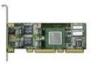
Intel® Integrated RAID Controller SRCS14L 2.2.6 SATA Connectors The SRCS14L provides four SATA signal connectors. 2.2.7 PCI Interface The SRCS14L has a 64-bit/66MHz PCI interface. The PCI connector is universally keyed for 3.3v or 5v signaling and is PCI 2.2 compliant. The controller is designed for optimal performance when inserted in a 64-bit/66MHz PCI expansion slot; however, it is backwards compatible with all 33MHz PCI expansion slots. 2.2.8 SRCS14L Jumpers The IIR controller normally comes ready to be installed into the computer motherboard immediately. However, jumper settings are available to: • Reprogram the RAID firmware that is located in the flash memory of the IIR controller. • Set the PCI bus speed (force 33 MHz or auto-negotiate 33/66 MHz). For jumper locations and settings, see Table 2: Controller Jumper Settings and Figure 2: Jumper Settings and Pin Numbers. Figure 2. Jumper Settings and Pin Numbers IOP Mode Select (J1) 1 Recovery Mode (pins 1-2) 2 Normal Mode (pins 2-3) 3 PCI Bus Speed (J4) 1 Force 33 MHz (pins 1-2) 2 Auto-negotiate 33 or 66 MHz (pins 2-3) 3 10 Technical Product Specification
-
 1
1 -
2
-
3
-
4
-
 5
5 -
 6
6 -
 7
7 -
 8
8 -
 9
9 -
 10
10 -
 11
11 -
 12
12 -
 13
13 -
 14
14 -
 15
15 -
16
-
17
-
18
-
19
-
20
-
21
-
22
-
23
-
24
-
25
-
26
-
27
-
28
-
29
-
30
-
31
-
32
-
33
 |
 |
