Intel SRCSAS18E User Guide - Page 38
Intel® RAID Controller SRCSAS18E Characteristics
 |
UPC - 675900727472
View all Intel SRCSAS18E manuals
Add to My Manuals
Save this manual to your list of manuals |
Page 38 highlights
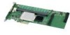
3 Intel® RAID Controller SRCSAS18E Characteristics This chapter describes the characteristics of the Intel® RAID Controller SRCSAS18E. The Intel® RAID Controller SRCSAS18E is a dual phys SAS PCI Express* storage adapter that is used in a system with a PCI Express slot. PCI Express goes beyond the PCI specification in that it is intended as a unifying I/O architecture for various systems: desktops, workstations, mobile, server, communications, and embedded devices. Figure 8 displays the connectors and headers on the controller and Table 2 describes them. J1 J15 Figure 8. Card Layout s Table 2. Jumper Descriptions Jumper Description J1 UART J5 I2C SAF-TE J6 BIOS disable Type Comments 3-pin Factory debug use only. connector 3-pin keyed connector SAF-TE OOB enclosure management. Warning: Do not connect to a non-expander SAS backplane. Doing so may cause data loss. 2-pin connector No jumper: Uses BIOS determination (default). Jumper installed: BIOS is disabled. 19 Intel® RAID Controller SRCSAS18E User's Guide
-
 1
1 -
2
-
3
-
4
-
5
-
6
-
7
-
8
-
9
-
10
-
11
-
12
-
13
-
14
-
15
-
16
-
17
-
18
-
19
-
20
-
21
-
22
-
23
-
24
-
25
-
26
-
27
-
28
-
29
-
30
-
31
-
32
-
 33
33 -
 34
34 -
 35
35 -
 36
36 -
 37
37 -
 38
38 -
 39
39 -
 40
40 -
 41
41 -
 42
42 -
 43
43 -
44
 |
 |
