Intel SRCSAS18E User Guide - Page 39
Characteristics, Table 2. Jumper Descriptions, Table 3. Card Characteristics - processors
 |
UPC - 675900727472
View all Intel SRCSAS18E manuals
Add to My Manuals
Save this manual to your list of manuals |
Page 39 highlights
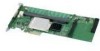
Table 2. Jumper Descriptions Jumper Description J7 Set Mode 0 J10 Dirty cache LED J15 Debug header J18 I2C SES2 Type Comments 2-pin connector Mode 0 holds the I/O processor in reset to allow firmware recovery. No jumper: Normal operational mode. Jumper: Mode 0 for firmware recovery. Requires a firmware recovery utility and firmware image file. 2-pin Connect to enclosure LED to indicate data in connector cache has not been written to disk. 4-pin Factory debug use only connector 4-pin keyed SES2 OOB enclosure management connector Characteristics Table 3 shows the general characteristics for the RAID Controller SRCSAS18E. Table 3. Card Characteristics Flash ROM1 SAS Data Transfers NVRAM SATA2 Features SAS Features SAS 1.0 SAS 1.1 SATA 1.0 Yes Up to 3 Gbits/s Yes per lane • 3 Gbits/s PSP, Yes Yes Yes SATA SMP, • Staggered STD spin-up • Hot-plug • Native command queing (NCQ) 2 • Activity and fault indicators • Port selector 1. For boot code and firmware. 2. NCQ is available only with TA D46199-003 or later. The RAID Controller SRCSAS18E ensures data integrity by intelligently validating the compatibility of the SAS domain. Intel® RAID Controller SRCSAS18E User's Guide 20
-
 1
1 -
2
-
3
-
4
-
5
-
6
-
7
-
8
-
9
-
10
-
11
-
12
-
13
-
14
-
15
-
16
-
17
-
18
-
19
-
20
-
21
-
22
-
23
-
24
-
25
-
26
-
27
-
28
-
29
-
30
-
31
-
32
-
33
-
 34
34 -
 35
35 -
 36
36 -
 37
37 -
 38
38 -
 39
39 -
 40
40 -
 41
41 -
 42
42 -
 43
43 -
 44
44
 |
 |
