Intel TIGPT1U Product Specification - Page 40
Extended Front Panel System Board
 |
UPC - 735858166249
View all Intel TIGPT1U manuals
Add to My Manuals
Save this manual to your list of manuals |
Page 40 highlights
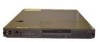
Extended Front Panel System Board Intel® Carrier Grade Server TIGPT1U TPS 4. Extended Front Panel System Board This chapter describes the basic functions and interface requirements of the Extended Front Panel system board that is designed for the Intel® Carrier Grade Server TIGPT1U. 4.1 Features Four switches to control power-on, reset, NMI, and the system ID LED One system ID LED that can be controlled remotely or by the system ID switch Two system activity LEDs that indicate power-on and NIC activity Two hard drive activity/fault LEDS that indicate activity/fault status for drives 0 and 1 Four system fault LEDs that indicate critical, major, minor, and power system fault status Four system fault relays for external critical, major, minor, and power fault indicators Hot-swap circuitry for controlling power delivery to SCSI disk drives 0 and 1 Power distribution to SE7210TP1-E System Baseboard, drive carrier assemblies, and hot plug disk drives 1 and 2 4.2 Chapter Structure and Outline The information contained in this chapter is organized into eight sections. The information is presented in a modular format, with numbered headings for each major topic and subtopic. The content of each section is summarized as follows: Section 4.3: Introduction Provides an overview of the Intel® TIGPT1U extended front panel board, showing primary components and their relationships, and physical board layout diagrams. Section 4.4: Functional Description of Front Panel Switches, LEDs, and Relays Provides a functional description of the front panel switches, LEDs, and relays contained on the FPIO board. Section 4.5: Connector Information Provides information on all connectors contained on the extended front panel board. Gives signal descriptions and the corresponding electrical parameters for each input and output of a given connector. Section 4.6: SCSI Power Subsystem Provides information on the hard drive interface circuitry on the extended front panel board. The hard drive interface circuitry is designed to give the end user support for two SCSI hot-plug hard drives. The design enables easy use and replacement of the SCSI hard drives without powering down the system. Section 4.7: Specifications Describes the electrical, environmental and mechanical specifications. 30 Revision 1.0
-
 1
1 -
2
-
3
-
4
-
5
-
6
-
7
-
8
-
9
-
10
-
11
-
12
-
13
-
14
-
15
-
16
-
17
-
18
-
19
-
20
-
21
-
22
-
23
-
24
-
25
-
26
-
27
-
28
-
29
-
30
-
31
-
32
-
33
-
34
-
 35
35 -
 36
36 -
 37
37 -
 38
38 -
 39
39 -
 40
40 -
 41
41 -
 42
42 -
 43
43 -
 44
44 -
 45
45 -
46
-
47
-
48
-
49
-
50
-
51
-
52
-
53
-
54
-
55
-
56
-
57
-
58
-
59
-
60
-
61
-
62
-
63
-
64
-
65
-
66
-
67
-
68
-
69
-
70
-
71
-
72
-
73
-
74
-
75
-
76
-
77
-
78
-
79
-
80
-
81
-
82
-
83
-
84
-
85
-
86
-
87
-
88
-
89
 |
 |
