Invacare RPS350-1 Owners Manual - Page 10
Assembly
 |
View all Invacare RPS350-1 manuals
Add to My Manuals
Save this manual to your list of manuals |
Page 10 highlights
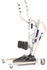
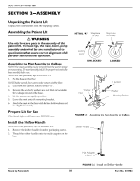
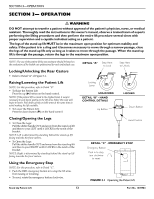
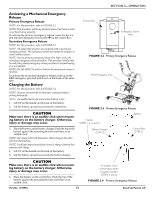
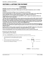
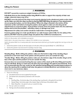
SECTION 2-ASSEMBLY SECTION 2-ASSEMBLY Unpacking the Patient Lift Unpack the components from the shipping carton. Assembling the Patient Lift ƽ WARNING Use only Invacare parts in the assembly of this patient lift. The base legs, the mast, boom, pump assembly and swivel bar are manufactured to specifications that assure correct alignment of all parts for safe functional operation. Assembling the Mast Assembly to the Base NOTE: The mast assembly may be removed from the base for storage or transporting. The mast assembly MUST be properly secured to the base assembly before use. NOTE: For this procedure, refer to FIGURE 2.1. 1. Put the base on the floor. NOTE: Make sure all four casters make contact with the floor. 2. Lock both rear casters. Refer to Detail "A". 3. Remove the hex bolt, washers and nut that are located in the U‐shape cut‐out of the base. 4. Lift the mast to an upright position. 5. Lower the mast onto the mounting bracket. 6. Attach the mast to the base with the hex bolt, washers and nut. Tighten securely. Prepare Lift for Use Check and tighten all hardware BEFORE use. Install the Shifter Handle NOTE: For this procedure, refer to FIGURE 2.2. 1. Remove the shifter handle from the packaging carton. 2. Thread the shifter handle onto the male adapter on the base. DETAIL "A" Step Here to Lock Step Here to Unlock Locking Lever UNLOCKED LOCKED Washer Nut Hex Bolt Washer Mounting Bracket FIGURE 2.1 Assembling the Mast Assembly to the Base Shifter Handle Stand Up Patient Lift Male Adapter in Base FIGURE 2.2 Install the Shifter Handle 10 Part No. 1078984
-
 1
1 -
2
-
3
-
4
-
 5
5 -
 6
6 -
 7
7 -
 8
8 -
 9
9 -
 10
10 -
 11
11 -
 12
12 -
 13
13 -
 14
14 -
 15
15 -
16
-
17
-
18
-
19
-
20
-
21
-
22
-
23
-
24
 |
 |
