Invacare SOLARA3GLS1 Owners Manual - Page 89
Wheel Locks/anti-tippers
 |
View all Invacare SOLARA3GLS1 manuals
Add to My Manuals
Save this manual to your list of manuals |
Page 89 highlights
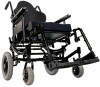
DETAIL "A" TOP VIEW 13 WHEEL LOCKS/ANTI-TIPPERS Wheel Lock Mounting Bracket Socket Screws (Behind Handle) Socket Screws Wheel Lock Assembly Wheel Lock Assembly Wheel Lock Shoe Wheel Lock Shoe Rear Wheel FIGURE 1 Wheel Lock Adjustment - Push to Lock or Pull to Lock Wheel locks Footlock When changing the position of the rear wheels, the wheel locks MUST be repositioned. Before adjusting or replacing the wheel lock assemblies, ensure that the tires are inflated to the recommended p.s.i on the side wall of the tire. 1. Loosen, but DO NOT remove the four mounting screws (two mounting screws on each side) that secure the wheel lock bracket to the wheelchair frame. (Detail "A") 2. Measure the distance between the wheel lock shoe and the rear wheel. 3. Slide the wheel lock bracket along the wheelchair frame until the measurement between the wheel lock shoe and rear wheel is approximately 1.25 inches. If 1.25 inch measurement is not achievable, perform the following: A. Remove the mounting screw, washers and locknut that secure the connecting wheel link to the footlock lever (Detail "B"). Part No 1154295 89 Invacare® Solara®3G/Spree 3G Wheelchair
-
 1
1 -
2
-
3
-
4
-
5
-
6
-
7
-
8
-
9
-
10
-
11
-
12
-
13
-
14
-
15
-
16
-
17
-
18
-
19
-
20
-
21
-
22
-
23
-
24
-
25
-
26
-
27
-
28
-
29
-
30
-
31
-
32
-
33
-
34
-
35
-
36
-
37
-
38
-
39
-
40
-
41
-
42
-
43
-
44
-
45
-
46
-
47
-
48
-
49
-
50
-
51
-
52
-
53
-
54
-
55
-
56
-
57
-
58
-
59
-
60
-
61
-
62
-
63
-
64
-
65
-
66
-
67
-
68
-
69
-
70
-
71
-
72
-
73
-
74
-
75
-
76
-
77
-
78
-
79
-
80
-
81
-
82
-
83
-
 84
84 -
 85
85 -
 86
86 -
 87
87 -
 88
88 -
 89
89 -
 90
90 -
 91
91 -
 92
92 -
 93
93 -
 94
94 -
95
-
96
-
97
-
98
-
99
-
100
-
101
-
102
-
103
-
104
-
105
-
106
-
107
-
108
-
109
-
110
-
111
-
112
-
113
-
114
-
115
-
116
-
117
-
118
-
119
-
120
-
121
-
122
-
123
-
124
 |
 |
