Invacare TRSX5RC Owners Manual - Page 78
Installing the Wheel Lock Extension Handle, Detail A, Detail B
 |
View all Invacare TRSX5RC manuals
Add to My Manuals
Save this manual to your list of manuals |
Page 78 highlights
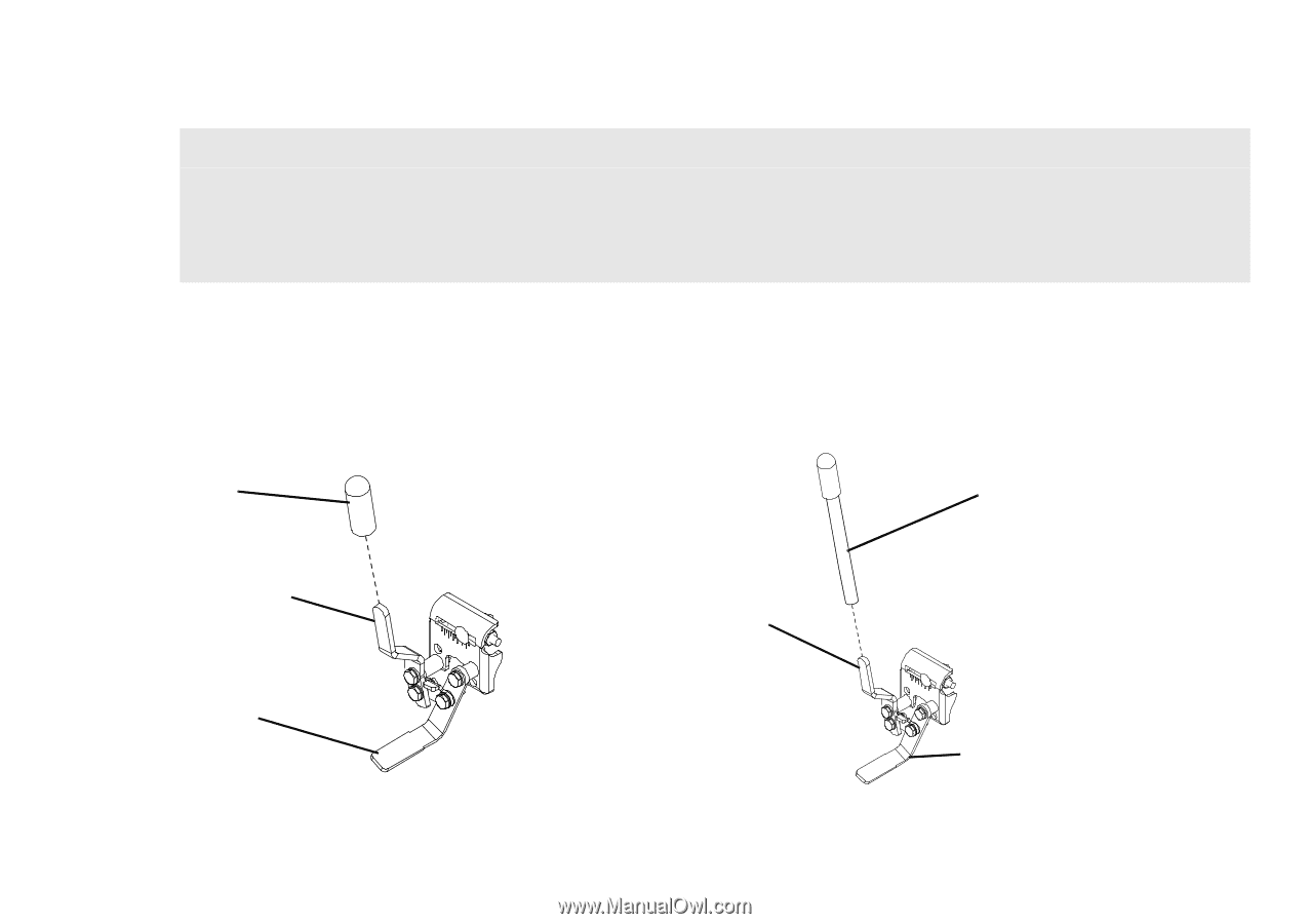
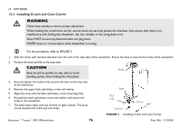
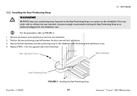
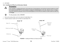
13 OPTIONS 13.4 Installing the Wheel Lock Extension Handle ƽ WARNING If the wheelchair is equipped with push to lock wheel locks, elevating legrests, and wheel lock extension handles, the wheel lock extension handles MUST be removed before swinging the elevating legrests to the side, otherwise injury or damage may result. Interference between the top of the elevating legrest and the wheel lock extension handle causes the wheel lock to disengage. For this procedure, refer to FIGURE 4 1. Remove the existing rubber tip from the wheel lock handle (Detail "A"). 2. Install the extension handle over the wheel lock handle (Detail "B"). Detail "A" Rubber Tip Detail "B" Wheel Lock Extension Handle Wheel Lock Handle Wheel Lock Handle Wheel Lock FIGURE 4 Installing the Wheel Lock Extension Handle Invacare® Tracer® SX5 Wheelchair 78 Wheel Lock Part No. 1110550
-
 1
1 -
2
-
3
-
4
-
5
-
6
-
7
-
8
-
9
-
10
-
11
-
12
-
13
-
14
-
15
-
16
-
17
-
18
-
19
-
20
-
21
-
22
-
23
-
24
-
25
-
26
-
27
-
28
-
29
-
30
-
31
-
32
-
33
-
34
-
35
-
36
-
37
-
38
-
39
-
40
-
41
-
42
-
43
-
44
-
45
-
46
-
47
-
48
-
49
-
50
-
51
-
52
-
53
-
54
-
55
-
56
-
57
-
58
-
59
-
60
-
61
-
62
-
63
-
64
-
65
-
66
-
67
-
68
-
69
-
70
-
71
-
72
-
 73
73 -
 74
74 -
 75
75 -
 76
76 -
 77
77 -
 78
78 -
 79
79 -
 80
80
 |
 |