JBL 305P MkII 3 Series MkII Owners Manual - English - Page 13
Input Panel, Right And Left Xlr Inputs, Input Sensitivity Switch, Volume Control, Crossover Frequency
 |
View all JBL 305P MkII manuals
Add to My Manuals
Save this manual to your list of manuals |
Page 13 highlights
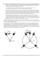
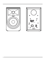
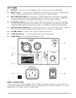
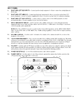
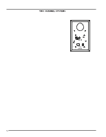
INPUT PANEL 6. RIGHT AND LEFT XLR INPUTS - Connect professional equipment to these connectors using balanced XLR plugs. 7. RIGHT AND LEFT 6MM (¼") - Connect professional equipment to these connectors using 6mm (¼") balanced plugs. Connect consumer equipment to these connectors using 6mm (¼") unbalanced plugs. 8. RIGHT AND LEFT XLR OUTPUTS - Connect these outputs to the 3 Series MkII speakers or other powered speakers or power amplifier in your monitoring system. 9. INPUT SENSITIVITY SWITCH - Set this switch to the +4dBu setting when connecting professional equipment and sources with very high output. Set this switch to -10dBV when connecting to lower-level consumer-grade audio equipment. NOTE: When the LSR310S is used in a system with 3 Series MkII speakers, set the INPUT SENSITIVITY switch on the 305P, 306P, or 308P MkII to the -10dBV setting regardless of the LSR310S input sensitivity switch setting. 10. VOLUME CONTROL - Use this control to balance the volume of the subwoofer with the volume of the speakers in the system. 11. CROSSOVER FREQUENCY - This crossover provides three settings: 80Hz, XLF, and External. The 80Hz setting is recommended for use with studio monitors, including the 305P, 306P, or 308P MkII. The External setting allows use of an outboard active crossover. Select the XLF (Extended Low Frequency) setting to activate a circuit that emulates the bass tuning commonly applied to club playback systems. 12. POLARITY - Enables optional 180 degree polarity reversal of the subwoofer output to optimize the blend of the subwoofer with the main speakers according to relative speaker and listening positions. Select the setting that produces the greatest amount of bass when heard at the listening position. 13. POWER RECEPTACLE - Connect the included power cord to this receptacle. 14. POWER SWITCH - Set this switch to the ON position to operate the subwoofer. Set this switch to the OFF position when the subwoofer is not in use. 8 7 6 12 9 11 10 13 14 13
-
 1
1 -
2
-
3
-
4
-
5
-
6
-
7
-
 8
8 -
 9
9 -
 10
10 -
 11
11 -
 12
12 -
 13
13 -
 14
14 -
 15
15 -
 16
16 -
 17
17 -
 18
18 -
19
-
20
-
21
-
22
 |
 |
