JET Tools GH-1440-1 User Manual - Page 17
Feed and thread selection, Change gears replacement, Automatic feed operation and, feed changes
 |
View all JET Tools GH-1440-1 manuals
Add to My Manuals
Save this manual to your list of manuals |
Page 17 highlights
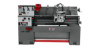
11.2 Feed and thread selection 1. Refer to the feed and thread charts found on the gear box faceplate (A, Fig. 18 and sect. 13.0 of this manual). 2. Move levers (B, C, D, E, F, Fig. 18) to the appropriate positions according to the chart. 11.3 Change gears replacement The 25T, 127T, 50T gears are installed in the end gear compartment when delivered from the factory. This combination will cover most inch feeds and threads under normal circumstances. The 30T, 32T, and two 40T gears found in the tool box are used with different combinations as indicated on feed and thread tables (A, Fig. 18). 1. Disconnect machine from power source (unplug). 2. Open the door on the left end of the headstock. 3. Loosen nuts (A & B, Fig. 19). 4. Move quadrant (C, Fig. 19) out of the way and hold in place temporarily by tightening nut (B, Fig. 19). 5. Remove hex socket cap screws (D and/or E, Fig. 19), depending on which gear is to be changed. 6. Install new gear(s) and tighten in place with a hex socket cap screw. 7. Loosen nut (B, Fig. 19), move quadrant back so teeth mesh on gears, and tighten nuts (A & B, Fig. 19). CAUTION: Make sure there is a backlash of .002"-.003" between gears. Setting the gears too tight will cause excessive noise and wear. 8. Close the door and connect machine to power source. 11.4 Automatic feed operation and feed changes 1. Move the forward/reverse selector (A, Fig. 20) up or down depending on desired direction. 2. Set selector levers (A, B, C, D, Fig. 21) to desired rate. Note: For feeding, lever (D) will be set at "F" or "D", depending on desired feed rate. 17 Figure 18 Figure 19 Figure 20
-
 1
1 -
2
-
3
-
4
-
5
-
6
-
7
-
8
-
9
-
10
-
11
-
 12
12 -
 13
13 -
 14
14 -
 15
15 -
 16
16 -
 17
17 -
 18
18 -
 19
19 -
 20
20 -
 21
21 -
 22
22 -
23
-
24
-
25
-
26
-
27
-
28
-
29
-
30
-
31
-
32
-
33
-
34
-
35
-
36
-
37
-
38
-
39
-
40
-
41
-
42
-
43
-
44
-
45
-
46
-
47
-
48
-
49
-
50
-
51
-
52
-
53
-
54
-
55
-
56
-
57
-
58
-
59
-
60
-
61
-
62
-
63
-
64
-
65
-
66
-
67
-
68
 |
 |
