JVC DLA-X70R Instructions - Page 16
Controls and features continued
 |
View all JVC DLA-X70R manuals
Add to My Manuals
Save this manual to your list of manuals |
Page 16 highlights
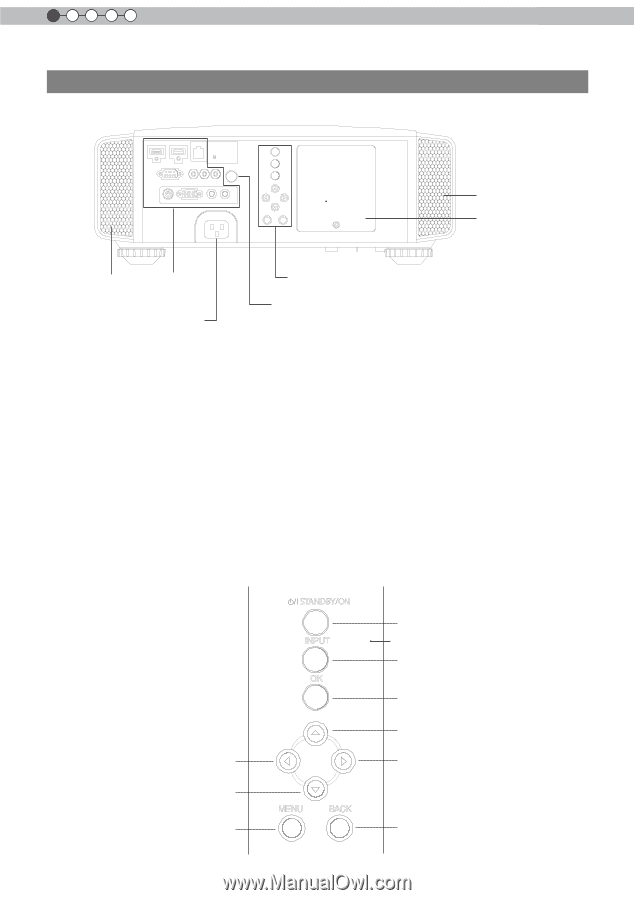
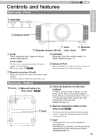
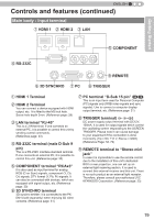
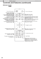
1 Getting started Controls and features (continued) Main body - Rear ⑤ Inlets ⑨ Lamp Cover ⑤ Inlets ⑧ Input terminal ⑫ Power input terminal ⑩ Operation panel ⑪ Light receiving section of the remote control (rear) ⑧ Input terminal There is also a terminal other than the input terminal for video images, such as those used for controlling or optional equipment. Please see "About input terminals" for detailed information about terminals. (Reference page: 19) ⑨ Lamp Cover When replacing the light source lamp, remove this cover. (Reference page: 78) ⑩ Operation panel See the following illustration "Control panel" for more details. ⑪ Light receiving section of the remote control (rear) Please aim the remote control at this section when using. (*) There is also a light receiving section at the rear. ⑫ Power input terminal This is the power input terminal. It is connected via the supplied power cord. (Reference page: 34) ■ Operation panel STANDBY/ON INPUT OK Left button Down button To display the menu MENU BACK To turn on/off the power To switch input To select or confirm Up button Right button To return to the previous menu 16
-
 1
1 -
2
-
3
-
4
-
5
-
6
-
7
-
8
-
9
-
10
-
 11
11 -
 12
12 -
 13
13 -
 14
14 -
 15
15 -
 16
16 -
 17
17 -
 18
18 -
 19
19 -
 20
20 -
 21
21 -
22
-
23
-
24
-
25
-
26
-
27
-
28
-
29
-
30
-
31
-
32
-
33
-
34
-
35
-
36
-
37
-
38
-
39
-
40
-
41
-
42
-
43
-
44
-
45
-
46
-
47
-
48
-
49
-
50
-
51
-
52
-
53
-
54
-
55
-
56
-
57
-
58
-
59
-
60
-
61
-
62
-
63
-
64
-
65
-
66
-
67
-
68
-
69
-
70
-
71
-
72
-
73
-
74
-
75
-
76
-
77
-
78
-
79
-
80
-
81
-
82
-
83
-
84
-
85
-
86
-
87
-
88
-
89
-
90
-
91
-
92
-
93
-
94
-
95
-
96
 |
 |