JVC DT-N24F Instruction Manual - Page 17
External Control
 |
View all JVC DT-N24F manuals
Add to My Manuals
Save this manual to your list of manuals |
Page 17 highlights
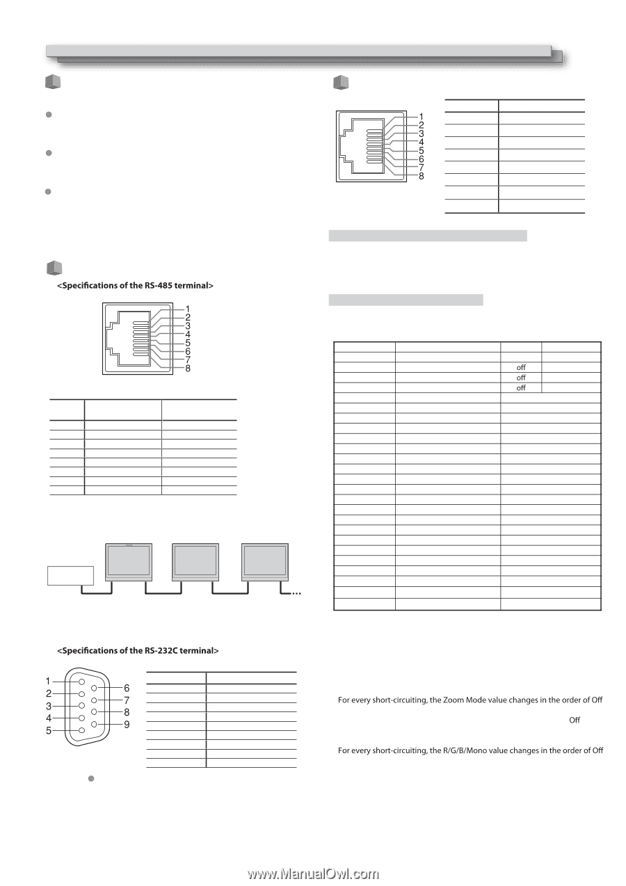
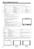
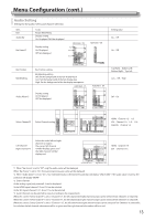
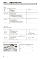
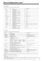
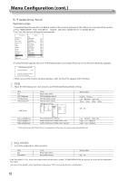
External Control About the external control This monitor has three external control terminals. RS-485 terminal (RJ-45): Controls the monitor with the RS-485 system. The terminal is to connect with TallyMan system of UMD application. RS-232C terminal (D-sub 9-pin): Controls the monitor with the RS-232C system (TallyMan) The terminal is to connect with TallyMan system of UMD application. Make contact terminal (RJ-45): Controls the monitor by short-circuiting the corresponding pin terminal to the GND pin terminal, or disconnecting (opening) it. The terminal is to assign functions for GPI controlling. Using the UMD control This is a female terminal. Pin No. IN terminal signal 1 TXD + 2 TXD - 3 RXD + 4 NC 5 NC 6 RXD - 7 NC 8 GND OUT terminal signal TXD + TXD - RXD + NC NC RXD - NC GND TallyMan RS-485 IN RS-485 RS-485 RS-485 RS-485 RS-485 OUT IN OUT IN OUT Using the GPI control This is a female terminal. Pin No 1 2 3 4 5 6 7 8 Pin name GPI 1 GPI 2 GPI 3 GPI 4 GPI 5 GPI 6 NC GND To assign the functions to the pin terminals 1 Select "GPI" on the Main Menu. 2 Set "GPI control" to "ON". 3 Select a pin name ("Pin1" - "Pin6") for which you want to assign a function, then select the function you want to assign. Operation of the external control 1 Operate each function by short-circuiting the corresponding pin terminal to the 8th pin terminal (GND) or opening it. Display Functions to be controlled Opening - Red Tally Tally light red Green Tally Tally light green Yellow Tally Tally light yellow Aspect Ratio Changes the aspect ratio. Scan Mode Changes the scan mode Zoom Mode Changes zoom mode Mute Mute setting Freeze Frame Freeze Frame setting Time code Time code display Zebra Zebra display Vector Vector display Audio Bar Audio Bar display Histogram Histogram display False Color False Color display AFD AFD display H/V Delay H/V Delay display Marker Marker display Color Bar Color Bar display UMD UMD display Audio Alarm Audio Alarm display Color Temp Color Temp setting R/G/B/Mono R/G/B/Mono setting Flip Mode Flip Mode setting Odd/Even Frame Odd/Even Mode setting Short-circuiting - Red Green Yellow *1 *2 *3 *4 *4 *4 *4 *4 *4 *4 *4 *4 *4 *4 *4 *4 *4 *5 *6 *7 *8 This is a female terminal. Pin No. 1 2 3 4 5 6 7 8 9 Signal NC RXD TXD NC GND NC RTS CTS NC The 7th terminal and the 8th terminal are connected. *1 For every short-circuiting, the Aspect Ratio value changes in the order of 16:9 ¹ 4:3 *2 For every short-circuiting, the Scan Mode value changes in the order of Normal ¹ Overscan ¹ Native *3 ¹ Zoom1 ¹ Zoom2 *4 For every short-circuiting, the value changes in the order of On ¹ *5 For every short-circuiting, the Color Temp value changes in the order of 6500K ¹ 5600K ¹ 9300K ¹ User *6 ¹ Blue Only ¹ Red Only ¹ Green Only ¹ Mono *7 For every short-circuiting, the Flip Mode value changes in the order of Off ¹ H Llip ¹ V Flip ¹ H/V Flip *8 For every short-circuiting, the Odd/Even Frame Mode value changes in the order of Off ¹ Odd Mode ¹ Even Mode 17
-
 1
1 -
2
-
3
-
4
-
5
-
6
-
7
-
8
-
9
-
10
-
11
-
 12
12 -
 13
13 -
 14
14 -
 15
15 -
 16
16 -
 17
17 -
 18
18 -
 19
19 -
 20
20 -
 21
21 -
 22
22 -
23
-
24
 |
 |