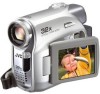
JVC GR-D372 Instructions - Page 9
Controls, Connectors, Indicators, Other Parts - review
 |
UPC - 046838026935
View all JVC GR-D372 manuals
Add to My Manuals
Save this manual to your list of manuals |
Page 9 highlights
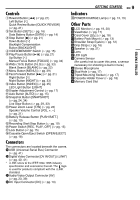
Controls 1Rewind Button [1] (੬ pg. 21) Left Button [1] Quick Review Button [QUICK REVIEW] (੬ pg. 21) 2Set Button [SET] (੬ pg. 16) Data Battery Button [DATA] (੬ pg. 14) 3Stop Button [7] (੬ pg. 21) Down Button [4] Backlight Compensation Button [BACKLIGHT] 4VIDEO/MEMORY Switch (੬ pg. 15) 5Play/Pause Button [6] (੬ pg. 21) Up Button [3] Manual Focus Button [FOCUS] (੬ pg. 34) 6Wide (16:9) Button [16.9] (੬ pg. 33) Blank Search [BLANK] (੬ pg. 22) 7Menu Button [MENU] (੬ pg. 29) 8Fast-Forward Button [¡] (੬ pg. 21) Right Button [2] Night Button [NIGHT] (੬ pg. 33) 9Index Button [INDEX] (੬ pg. 25) LED Light Button [LIGHT] !Diopter Adjustment Control (੬ pg. 17) "Auto Button [AUTO] (੬ pg. 15) #Snapshot Button [SNAPSHOT] (੬ pg. 24, 34) Live Slow Button (੬ pg. 29, 33) $Power Zoom Lever [T/W] (੬ pg. 20) Speaker Volume Control [VOL. +, -] (੬ pg. 21) %Battery Release Button [PUSH BATT.] (੬ pg. 13) &Recording Start/Stop Button (੬ pg. 19) (Power Switch [REC, PLAY, OFF] (੬ pg. 15) )Lock Button (੬ pg. 15) ~Cassette Open/Eject Switch [OPEN/EJECT] (੬ pg. 18) Connectors The connectors are located beneath the covers. +USB (Universal Serial Bus) Connector (੬ pg. 41) ,Digital Video Connector [DV IN/OUT] (i.LINK*) (੬ pg. 40, 41) * i.LINK refers to the IEEE1394-1995 industry specification and extensions thereof. The logo is used for products compliant with the i.LINK standard. -Audio/Video Output Connector [AV] (੬ pg. 23, 39) .DC Input Connector [DC] (੬ pg. 13) GETTING STARTED EN 9 çIndicators POWER/CHARGE Lamp (੬ pg. 13, 19) Other Parts éLCD Monitor (੬ pg. 19, 20) èViewfinder (੬ pg. 17) êCard Cover [ ] (੬ pg. 18) ëBattery Pack Mount (੬ pg. 13) íShoulder Strap Eyelet (੬ pg. 12) ìGrip Strap (੬ pg. 16) îSpeaker (੬ pg. 21) ïLens ñLED Light óCamera Sensor (Be careful not to cover this area, a sensor necessary for shooting is built-in here.) òStereo Microphone ôStud Hole (੬ pg. 17) öTripod Mounting Socket (੬ pg. 17) õCassette Holder Cover (੬ pg. 18) úMemory Card Slot GETTING STARTED
-
 1
1 -
2
-
3
-
 4
4 -
 5
5 -
 6
6 -
 7
7 -
 8
8 -
 9
9 -
 10
10 -
 11
11 -
 12
12 -
 13
13 -
 14
14 -
15
-
16
-
17
-
18
-
19
-
20
-
21
-
22
-
23
-
24
-
25
-
26
-
27
-
28
-
29
-
30
-
31
-
32
-
33
-
34
-
35
-
36
-
37
-
38
-
39
-
40
-
41
-
42
-
43
-
44
-
45
-
46
-
47
-
48
-
49
-
50
-
51
-
52
 |
 |
