JVC GR-D775 Instructions - Page 9
Controls, Connectors, Indicators, Other Parts - digital
 |
UPC - 046838028595
View all JVC GR-D775 manuals
Add to My Manuals
Save this manual to your list of manuals |
Page 9 highlights
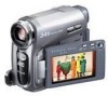
Controls 11 : Left/Rewind (1) (੬ pg. 21)/ Quick Review [QUICK REVIEW] (੬ pg. 18) 2 : Right/Fast-Forward (¡) (੬ pg. 21)/ LED Light [LIGHT] (੬ pg. 36) 3 : Up/Play/Pause (6) (੬ pg. 21)/ Manual Focus [FOCUS] (੬ pg. 37) 4 : Down/Stop (7) (੬ pg. 21)/ Backlight Compensation [ ] (੬ pg. 38)/ Spot Exposure (੬ pg. 39) Press down : SET 2VIDEO/MEMORY Switch 316:9 Wide Screen Button [16:9] (੬ pg. 17) Blank Search [BLANK] (੬ pg. 22) Index Button [INDEX] (੬ pg. 27) 4Menu Button [MENU] (੬ pg. 31) 5Data Battery Button [DATA] (੬ pg. 14) 6Auto Button [AUTO] (੬ pg. 20) 7Diopter Adjustment Control (੬ pg. 15) 8Snapshot Button [SNAPSHOT] (੬ pg. 26, 36) 9Power Zoom Lever [T/W] (੬ pg. 19) Speaker Volume Control [VOL. +, -] (੬ pg. 21) !Recording Start/Stop Button [START/STOP] (੬ pg. 18) "Power Switch [REC, PLAY, OFF] #Lock Button $Battery Release Button [BATT.] (੬ pg. 13) %Cassette Open/Eject Switch [OPEN/EJECT] (੬ pg. 16) Connectors &USB (Universal Serial Bus) Connector (੬ pg. 44) (Digital Video Connector [DV IN/OUT] (i.LINK*) (੬ pg. 43, 44) * i.LINK refers to the IEEE1394-1995 industry specification and extensions thereof. The logo is used for products compliant with the i.LINK standard. The connectors are located beneath the covers. )Audio/Video Output Connector [AV] (੬ pg. 23, 42) ~DC Input Connector [DC] (੬ pg. 13) GETTING STARTED EN 9 âIndicators POWER/CHARGE Lamp (੬ pg. 13) Other Parts äLCD Monitor (੬ pg. 8) ãViewfinder (੬ pg. 15) åCard Cover [ ] (੬ pg. 17) çBattery Pack Mount (੬ pg. 13) éShoulder Strap Eyelet (੬ pg. 12) èGrip Strap (੬ pg. 12) êSpeaker (੬ pg. 21) ëLens íLED Light (੬ pg. 36) ìCamera Sensor (Be careful not to cover this area, a sensor necessary for shooting is built-in here.) îRemote Sensor (੬ pg. 24, 25) ïStereo Microphone ñStud Hole (੬ pg. 15) óTripod Mounting Socket (੬ pg. 15) òCassette Holder Cover (੬ pg. 16) ôMemory Card Slot öConnector Cover Power Switch Position REC: To perform recording on the tape or in the memory card. OFF: To switch off the camcorder. PLAY: ● To play back a recording on the tape. ● To display a still image stored in the memory card or to transfer a still image stored in the memory card to a PC. VIDEO/MEMORY Switch Position VIDEO: To record on a tape or play back a tape. MEMORY: To record in a memory card or access data stored in a memory card. GETTING STARTED
-
 1
1 -
2
-
3
-
 4
4 -
 5
5 -
 6
6 -
 7
7 -
 8
8 -
 9
9 -
 10
10 -
 11
11 -
 12
12 -
 13
13 -
 14
14 -
15
-
16
-
17
-
18
-
19
-
20
-
21
-
22
-
23
-
24
-
25
-
26
-
27
-
28
-
29
-
30
-
31
-
32
-
33
-
34
-
35
-
36
-
37
-
38
-
39
-
40
-
41
-
42
-
43
-
44
-
45
-
46
-
47
-
48
-
49
-
50
-
51
-
52
 |
 |
