JVC GY-DV500U GY-DV500 User Manual - PDF (4,089KB) - Page 20
Rear - camcorder mini dv
 |
View all JVC GY-DV500U manuals
Add to My Manuals
Save this manual to your list of manuals |
Page 20 highlights
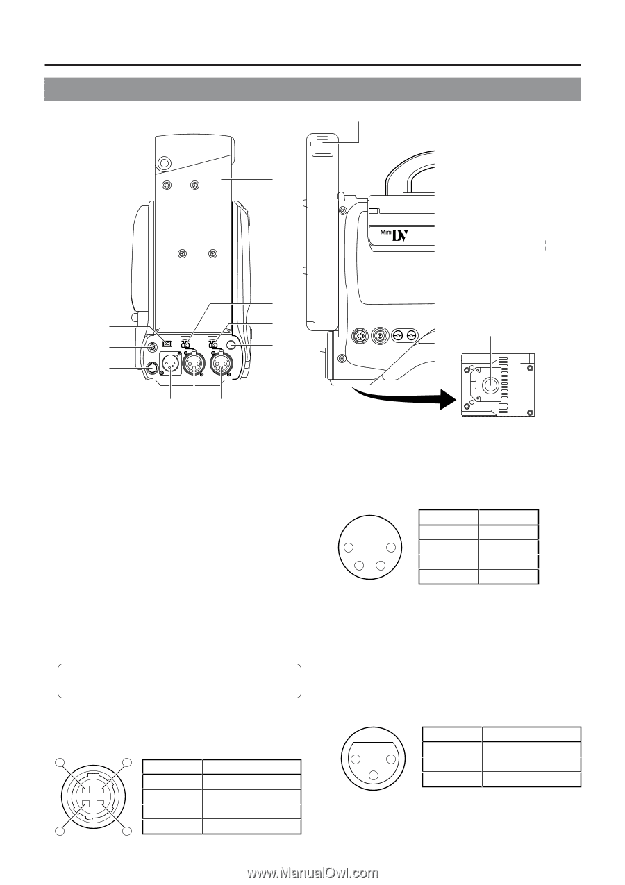
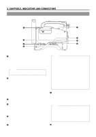
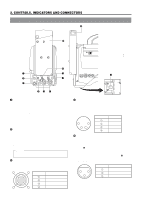
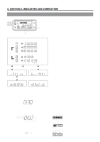
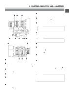
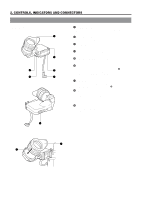
2. CONTROLS, INDICATORS AND CONNECTORS 2-5 Rear Section !1 PUSH 0 DV CAMCORDER GY-DV500 q w e EARPHONE DV CH-1 AUDIO IN CH-2 LINE MIC LINE MIC DC INPUT +48V ON +48V ON TALLY DC OUTPUT i o u Y/C OUT MONITOR OUT LINE OUT CH-1 CH-2 VTR REMOTE SYNC IN B TEST OUTPUT MIC LENS BREAKER rt y 1 [DV] connector Using a DV cable (optional), a digital video component with DV connector can be connected here. This connector is used for input and output of the DV signal or to input the VCR control signal from the digital video component with DV connector. • To record the DV signal from this connector, set the VCR Setup Menu item No. 126 INPUT SELECT to "IEEE1394". • To remote control the VCR with a VCR control signal from this connector, set the VCR Setup Menu item No. 050 REMOTE SELECT to "IEEE1394". 2 [EAR.] earphone jack This is a stereo mini-jack for connecting an audio monitoring earphone. Plug in an earphone or headphone with a 3.5 mm diameter plug. (Monaural mini jack) The earphone can also be used to monitor alarm tones depending on situations. The sound from the monitoring loudspeaker is interrupted when an earphone is connected here. Memo: Only the left-channel sound is heard when a stereo minijack is used. 3 [DC OUTPUT] connector Power output connector to a wireless microphone transmitter, etc. The supply voltage is identical to the voltage supplied to the unit (DC 12V max. 0.1 A). 4 1 3 2 (Surface profile) No. Signal 1 GND 2 - 3 - 4 DC +12V (power through) 20 Bottom side 4 [DC INPUT] connector (XLR 4-pin) Power input connector for 12 V DC. Connect with the AAP250 optional AC power adapter. When a cable is connected here, the power supply from the battery pack is interrupted and the source is switched to the power supplied through this connector. No. Signal 1 4 1 GND 2 - 23 3 - 4 +12V 5 [CH-1 AUDIO IN] CH-1 audio input connector (XLR 3-pin) Connect the external audio equipment or microphone to this connector. Set the CH-1 AUDIO IN LINE/MIC select switch 8 according to the connected equipment. The audio signal input through this connector is recorded on the CH-1 audio channel. To record the audio of this connector, set the CH-1 AUDIO INPUT switch 7 on page 14 to "REAR". (AUDIO IN connector) 2 1 3 No. Signal 1 GND 2 HOT 3 COLD
-
 1
1 -
2
-
3
-
4
-
5
-
6
-
7
-
8
-
9
-
10
-
11
-
12
-
13
-
14
-
 15
15 -
 16
16 -
 17
17 -
 18
18 -
 19
19 -
 20
20 -
 21
21 -
 22
22 -
 23
23 -
 24
24 -
 25
25 -
26
-
27
-
28
-
29
-
30
-
31
-
32
-
33
-
34
-
35
-
36
-
37
-
38
-
39
-
40
-
41
-
42
-
43
-
44
-
45
-
46
-
47
-
48
-
49
-
50
-
51
-
52
-
53
-
54
-
55
-
56
-
57
-
58
-
59
-
60
-
61
-
62
-
63
-
64
-
65
-
66
-
67
-
68
-
69
-
70
-
71
-
72
-
73
-
74
-
75
-
76
-
77
-
78
-
79
-
80
-
81
-
82
-
83
-
84
-
85
-
86
-
87
-
88
-
89
-
90
-
91
-
92
-
93
-
94
-
95
-
96
 |
 |