JVC GY-DV5100U Instruction Manual - Page 19
Rear CH-1/CH-2 REAR AUDIO IN] CH-1/CH-2 Audio - gy dv5100
 |
View all JVC GY-DV5100U manuals
Add to My Manuals
Save this manual to your list of manuals |
Page 19 highlights
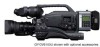
2. CONTROLS, INDICATORS AND CONNECTORS 2-5 Rear Section t y u PHONES DV INT DC OUT DC IN TALLY CH-1 CH-2 REAR AUDIO IN q re w 1 [TALLY] Tally lamp This lamp lights up when the GY-DV5100 enters the record mode. It blinks during the transition to the record mode. ● Use the BACK TALLY item on the OTHERS (2/2) menu screen to select whether or not the lamp should light and the lighting pattern. ☞ See "BACK TALLY" on page 87. 2 [CH-1/CH-2 REAR AUDIO IN] CH-1/CH-2 Audio input connector on the rear section Connect external audio equipment or a microphone to this connector. ● Set the CH-1/CH-2 REAR AUDIO IN switch B on page 16 in accordance with the connected equipment. ● To record the audio signal input through this connector, set the CH-1 or CH-2 AUDIO IN switch 0 on page 16 to "REAR". The audio from this connector is recorded on the channel set to "REAR". 2 1 3 No. Signal 1 GND 2 HOT 3 COLD 3 [DC IN] DC input connector (XLR 4-pin) Power input connector for 12 V DC. Connect to the optional AA-P250 power adapter. When a cable is connected here, the power supply from the battery pack is interrupted and the source is switched to the power supplied through this connector. 1 2 4 3 No. Signal 1 GND 2 - 3 - 4 +12V 4 [DC OUT] DC output connector Connector for power output to a wireless microphone transmitter, etc. The supply voltage is identical to the voltage supplied to the unit (DC 17 V max. 0.3 A). 4 1 No. Signal 1 GND 2 - 3 - 3 2 4 DC 12V (power through) (Surface profile) 5 [PHONES] Earphone jack This is a stereo mini-jack for connecting an earphone for audio monitoring. Plug in an earphone or headphone with a 3.5 mm diameter plug. The earphone can also be used to monitor alarm tones in accordance with the circumstances. The sound from the monitoring speaker is interrupted when an earphone is connected here. The audio channel to be output is selected with the AUDIO SELECT item on the AUDIO/VIDEO menu screen and MONITOR SELECT switch C on page 16. The audio output level is adjusted with the Audio monitor volume control 1 on page 12. MEMO: ● The volume of the alarm sound is set with the ALARM VR LEVEL item on the OTHERS (2/2) menu screen. ● When using a stereotype jack and stereo sound should be output, the following setting should be performed. Set the MONITOR SELECT switch to "MIX". Set the AUDIO MONITOR item on the AUDIO/VIDEO menu screen to STEREO. 6 [DV/INT]DV/INT selector switch This switch is used to select whether to connect the optional DV Disk Recorder to this camera or a digital video component to the 7 DV connector. DV: Connect a digital video component to the DV connector INT: Connect a DV Disk Recorder to the camera * Turn the camera off before using this switch. 7 [DV] connector Using a DV cable (optional), a digital video component with DV connector can be connected here. This connector is used for input and output of the DV signal or to input the VTR control signal from a digital video component with DV connector. To record the DV signal from this connector, set the unit to the VTR mode. (Press the MODE switch F on page 14 upward to turn on the VTR indicator.) ● Camera mode: The DV compressed signal (IEEE1394) of the camera image is output. ● VTR mode: The DV input signal from this connector can be recorded on tape. During playback, the tape playback DV compressed signal is output. MEMO: To receive FF/REW remote control signals from this connector, select the setting with the REM FF/REW MODE item on the OTHERS (1/2) menu screen. 19
-
 1
1 -
2
-
3
-
4
-
5
-
6
-
7
-
8
-
9
-
10
-
11
-
12
-
13
-
 14
14 -
 15
15 -
 16
16 -
 17
17 -
 18
18 -
 19
19 -
 20
20 -
 21
21 -
 22
22 -
 23
23 -
 24
24 -
25
-
26
-
27
-
28
-
29
-
30
-
31
-
32
-
33
-
34
-
35
-
36
-
37
-
38
-
39
-
40
-
41
-
42
-
43
-
44
-
45
-
46
-
47
-
48
-
49
-
50
-
51
-
52
-
53
-
54
-
55
-
56
-
57
-
58
-
59
-
60
-
61
-
62
-
63
-
64
-
65
-
66
-
67
-
68
-
69
-
70
-
71
-
72
-
73
-
74
-
75
-
76
-
77
-
78
-
79
-
80
-
81
-
82
-
83
-
84
-
85
-
86
-
87
-
88
-
89
-
90
-
91
-
92
-
93
-
94
-
95
-
96
-
97
-
98
-
99
-
100
-
101
-
102
-
103
 |
 |
