JVC KD-S25 Installation Manual - Page 2
Electrical Connections - manual for
 |
UPC - 046838036101
View all JVC KD-S25 manuals
Add to My Manuals
Save this manual to your list of manuals |
Page 2 highlights
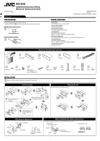
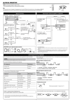
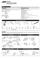
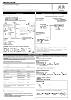
ELECTRICAL CONNECTIONS Make sure to disconnect the battery's negative terminal. • Be sure to ground this unit to the car's chassis again after installation. High Note: It is recommended to connect to the speakers with maximum power of more than 50 W (both at the rear and at the front, with an impedance of 4 Ω to 8 Ω). If the maximum power is less than 50 W, change "AMP GAIN" setting to prevent the speakers from being damaged (see page 23 of the INSTRUCTIONS). Heat sink Typical connections Antenna terminal Rear line out Rear ground terminal 15 A fuse To external components Connect only the front speakers if your speaker system is two-speaker system. White with black stripe Front speaker (left) White Gray with black stripe Front speaker (right) Gray Green with black stripe Rear speaker (left) Green Purple with black stripe Black Yellow *2 Red To metallic body or chassis of the car Ignition switch To a live terminal in the fuse block connecting to the car battery (bypassing the ignition switch) (constant 12 V) Fuse block To an accessory terminal in the fuse block Blue with white stripe To the remote lead of other equipment or automatic antenna if any (200 mA max.) Connecting the external amplifiers or subwoofer Remote lead Y-connector *1 Set "L/O MODE" to "REAR" (See page 23 of the INSTRUCTIONS.) Remote lead (blue with white stripe) To the remote lead of other equipment or automatic antenna if any JVC Amplifier Rear speakers or Set "L/O MODE" to "SUB.W" (See page 23 of the INSTRUCTIONS.) Remote lead JVC Amplifier Subwoofer Right Left Front speakers Rear speaker (right) Purple PRECAUTIONS on power supply and speaker connections *1 Not supplied for this unit. *2 Before checking the operation of this unit prior to installation, this lead must be connected, otherwise power cannot be turned on. *3 Firmly attach the ground wire to the metallic body or to the chassis of the car-to the place not coated with paint (if coated with paint, remove the paint before attaching the wire). Failure to do so may cause damage to the unit. *4 Signal cord (not supplied for this unit). Connecting the external components When connecting the external components, refer also to the manuals supplied for the components and adapter. CAUTION: Before connecting the external components, make sure that the unit is turned off. You can connect the following JVC components to the CD changer jack. JVC component Model name CD changer (CD-CH) HD RadioTM tuner box CH-X1500, etc. KT-HD300 When connecting more than one component (maximum: three), it is recommended that you connect the components in series as explained below. • XM Radio and SIRIUS satellite radio cannot be used together. When connecting two components in series *5 CD changer jack A KT-HD300*6 / KS-SRA100*6 / KS-BTA200 / XMDJVC100 B*5 CD-CH / KS-PD100 / KS-U57 / KS-U58 / KS-U100K You can also connect the following components through the various JVC adapters. • Connection cords may need to be purchased separately. When connecting three components in series Component Adapter Model name *5 Bluetooth device Bluetooth adapter iPod Interface adapter for iPod XMDirectTM Universal Tuner Box Smart Digital Adapter SIRIUS satellite radio SIRIUS satellite radio interface JVC SIRIUS PnP SIRIUS radio adapter Portable audio player with line output jacks Line input adapter Portable audio player with 3.5 mm (3/16") stereo AUX input adapter mini jack KS-BTA200 KS-PD100 XMDJVC100 KS-SRA100 KS-U100K KS-U57 KS-U58 CD changer jack A KT-HD300*6 / KS-SRA100*6 / XMDJVC100 B KS-BTA200 C*5 KS-PD100 / KS-U57 / KS-U58 / KS-U100K To disconnect the connector Hold the connector top tightly (1), then pull it out (2). HD RadioTM is a proprietary trademark of iBiquity Digital Corp. iPod is a trademark of Apple Inc., registered in the U.S. and other countries. *5 To use these components, set the external input setting correctly (see page 23 of the INSTRUCTIONS). *6 Power cannot be supplied to the component through the CD changer jack. You need to connect the power cord supplied for the component separately. It is not recommended to connect KS-U57/KS-U58/KS-U100K at C in series with XMDJVC100 and KS-BTA200. 2
-
 1
1 -
 2
2 -
 3
3 -
 4
4
 |
 |