JVC KD-X310BT Instruction Manual - Page 29
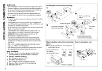
Part list for, installation, Wiring connection - microphone
 |
View all JVC KD-X310BT manuals
Add to My Manuals
Save this manual to your list of manuals |
Page 29 highlights
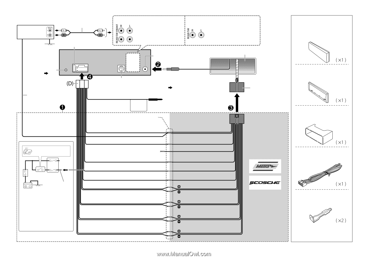
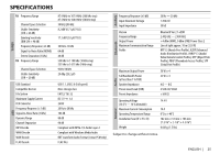
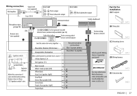
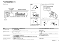
Wiring connection JVC Amplifier Signal cord (not supplied) Fuse (10 A) KD-X310BT Front output Rear/subwoofer output KD-X31MBS Rear/subwoofer output Antenna terminal Vehicle dashboard Part list for installation (A) Faceplate Microphone input jack ( 13) Remote wire (not supplied) Ignition switch Car fuse block Separate red wire Make this connection if your vehicle factory wiring harness does not have "12 V ignition switch" wire. (For KD-X31MBS) To the optional SiriusXM Vehicle Tuner (commercially available) ( 11) Light blue/yellow (For KD-X31MBS) STEERING WHEEL REMOTE Join the same color wires together. Blue/white: Remote (200 mA max.) Orange/white: Illumination To the steering wheel remote control adapter Recommended connection Blue: To power antenna Blue/white: To amplifier (Not used) Insulate to prevent short circuit Yellow: Battery 12 V Red: Ignition 12 V Black: Ground White: Front speaker (left) White/black Gray: Front speaker (right) Gray/black Green: Rear speaker (left) Green/black Purple: Rear speaker (right) Purple/black Factory wiring harness (vehicle) (B) Trim plate (C) Mounting sleeve Vehicle-specific Wiring Harness (separately purchased) (D) Wiring harness For more information: Metra Electronics: www.metraonline.com Scosche Industries: www.scosche.com (E) Extraction key ENGLISH | 27
-
 1
1 -
2
-
3
-
4
-
5
-
6
-
7
-
8
-
9
-
10
-
11
-
12
-
13
-
14
-
15
-
16
-
17
-
18
-
19
-
20
-
21
-
22
-
23
-
 24
24 -
 25
25 -
 26
26 -
 27
27 -
 28
28 -
 29
29 -
 30
30 -
 31
31 -
 32
32 -
 33
33 -
 34
34 -
35
-
36
-
37
-
38
-
39
-
40
-
41
-
42
-
43
-
44
-
45
-
46
-
47
-
48
-
49
-
50
-
51
-
52
-
53
-
54
-
55
-
56
-
57
-
58
-
59
-
60
-
61
-
62
-
63
-
64
-
65
-
66
-
67
-
68
-
69
-
70
-
71
-
72
-
73
-
74
-
75
-
76
-
77
-
78
-
79
-
80
-
81
-
82
 |
 |