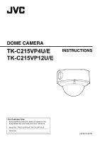
JVC TK-C215VP12U Instructions - Page 6

Table of Contents, Introduction, Installation and Connection, Others

Page 6 highlights

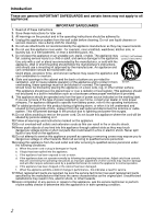
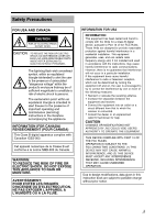
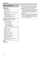
Introduction Table of Contents Introduction Safety Precautions 3 Characteristics 5 Table of Contents 6 Precautions for proper use of this product ... 7 Name of Parts 9 Setting the Switches and the Lens (TK-C215VP4U/E 12 Setting the Switches and the Lens (TK-C215VP12U/E 14 Installation and Connection System Example 16 About Connection Cables 17 Video signal cables 17 DC 12 V or AC 24 V power supply cable 17 Electrical Specifications of Alarm Input Terminals 18 The right sequence to connect and set the camera 19 Setting the switches 20 Mounting the base 21 Cable Connection 22 Mounting the camera unit 23 Adjusting the video image 25 Mounting the inner dome 30 Mounting the dome cover 30 Mounting the camera using the electrical box 31 Mounting the camera using the pipe ...... 32 White-spot correction 34 Others Specifications 36 ⅷ Before starting an important recording, be sure to perform a test recording in order to confirm that a normal recording is possible. ⅷ We will not provide any compensation whatsoever for the contents to be recorded or loss of opportunities when recording is not properly performed due to malfunction of the video camera, VTR, hard disk recorder or video tape. ⅷ Before touching the camera unit, make sure to touch the metal surface of the [MONITOR] terminal to discharge any static electricity from your body. Static electricity may cause the camera to malfunction. 6

  • 1
  • 2
  • 3
  • 4
  • 5
  • 6
  • 7
  • 8
  • 9
  • 10
  • 11
  • 12
  • 13
  • 14
  • 15
  • 16
  • 17
  • 18
  • 19
  • 20
  • 21
  • 22
  • 23
  • 24
  • 25
  • 26
  • 27
  • 28
  • 29
  • 30
  • 31
  • 32
  • 33
  • 34
  • 35
  • 36
  • 37
  • 38
  • 39
  • 40

6
Introduction
Introduction
Safety Precautions
....................................
3
Characteristics
..........................................
5
Table of Contents
......................................
6
Precautions for proper use of this product
... 7
Name of Parts
...........................................
9
Setting the Switches and the Lens
(TK-C215VP4U/E)
................................
12
Setting the Switches and the Lens
(TK-C215VP12U/E)
..............................
14
Installation and Connection
System Example
.....................................
16
About Connection Cables
.......................
17
Video signal cables
.............................
17
DC 12 V or AC 24 V
power supply cable
.........................
17
Electrical Specifications of
Alarm Input Terminals
.....................
18
The right sequence to connect and set the
camera
.................................................
19
Setting the switches
................................
20
Mounting the base
..................................
21
Cable Connection
...................................
22
Mounting the camera unit
.......................
23
Adjusting the video image
......................
25
Mounting the inner dome
........................
30
Mounting the dome cover
.......................
30
Mounting the camera using
the electrical box
..................................
31
Mounting the camera using the pipe
......
32
White-spot correction
..............................
34
Others
Specifications
.........................................
36
Table of Contents
±
Before starting an important recording, be
sure to perform a test recording in order to
confirm that a normal recording is possible.
±
We will not provide any compensation
whatsoever for the contents to be recorded or
loss of opportunities when recording is not
properly performed due to malfunction of the
video camera, VTR, hard disk recorder or
video tape.
±
Before touching the camera unit, make sure
to touch the metal surface of the [MONITOR]
terminal to discharge any static electricity
from your body. Static electricity may cause
the camera to malfunction.