Jensen PCR2500CS Owners Manual - Page 3
Installation Instructions/wiring Diagram - speakers
 |
View all Jensen PCR2500CS manuals
Add to My Manuals
Save this manual to your list of manuals |
Page 3 highlights
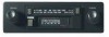
PCR2500 INSTALLATION INSTRUCTIONS/WIRING DIAGRAM Do You Need an Installation Kit? Inspect the radio opening as described below to determine if you need an installation kit. 1. Use the trimplate supplied with the radio to cover the existing dashboard opening. If it completely covers the opening, you can install the radio without an installation kit. If it does not cover the opening, you will need an installation kit (see page 4). 2. Check for sufficient space behind the dashboard for the radio chassis. Wiring the Radio 1. Place the radio near the dashboard so the wires can be led through the opening. 2. Carefully follow the wiring diagram, securing all connections with wire nuts or electrical tape. 3. Turn the unit on to confirm operation (vehicle ignition switch must be "on"). If unit does not operate, check all wiring until the problem is corrected, then turn unit off. 4. Adjust the AM Antenna Trimmer, located on the right side of the chassis, for optimum AM reception. a. Tune in a weak station around 1400 KHz on the AM band. b. Using a small screwdriver, slowly adjust the trimmer for maximum output from the radio. Antenna Connector WARNING! Never combine (bridge) outputs for use with 1 speaker. WARNING! Never ground negative speaker leads to chassis ground. CAUTION: Failure to wire exactly as shown may cause electrical damage. LEFT White/Black (-) White (+) Black Red 3A Gray/Black (-) Gray (+) RIGHT NOTE: The Antenna Trimmer only affects AM reception and will have no effect on FM reception. The Trimmer should only need adjusting when the radio is first installed and when a change is made to the vehicle antenna (replacing the mast, etc.). WIRING DIAGRAM Ground Connect to ground terminal. Accessory/Ignition Connect to existing radio wire or radio fuse. Fuses When replacing a fuse, make sure the new fuse is the correcttype (AGC) and amperage. Using an incorrect fuse could damage the radio. AM ANTENNA TRIMMER 3
-
 1
1 -
 2
2 -
 3
3 -
 4
4 -
 5
5 -
 6
6 -
 7
7 -
 8
8 -
 9
9 -
10
-
11
-
12
-
13
-
14
-
15
-
16
-
17
-
18
-
19
-
20
-
21
-
22
-
23
-
24
 |
 |
