Kenmore 4101 Use and Care Guide - Page 11
Setting, Surface, cont'd
 |
View all Kenmore 4101 manuals
Add to My Manuals
Save this manual to your list of manuals |
Page 11 highlights
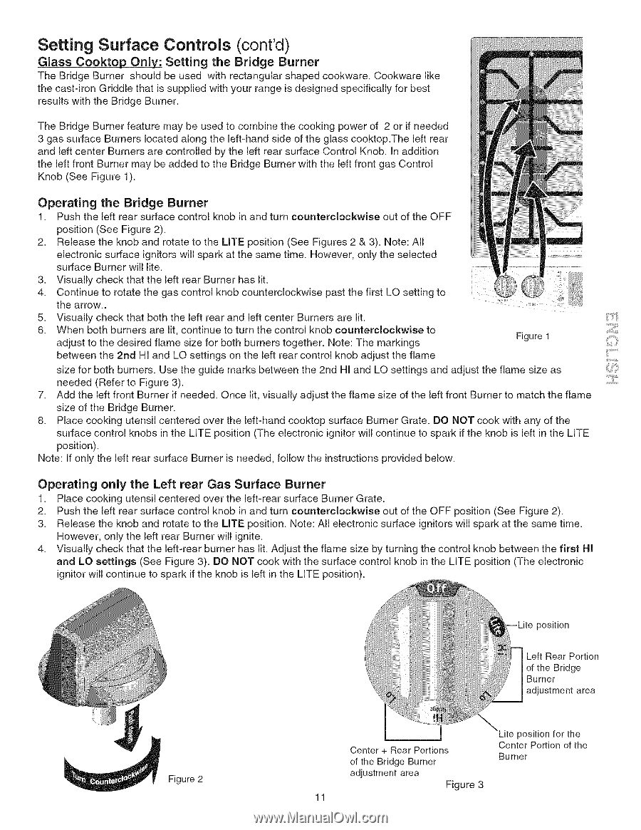
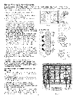
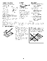
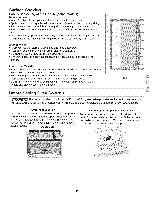
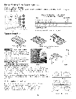
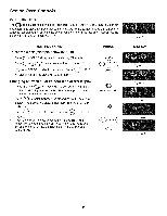
Setting Surface Controls (cont'd) Glass Cooktop Only;." Setting the Bridge Burner The Bridge Burner should be used with rectangular shaped cookware. Cookware like the cast-iron Griddle that is supplied with your range is designed specifically for best results with the Bridge Burner. The Bridge Burner feature may be used to combine the cooking power of 2 or if needed 3 gas surface Burners located along the left-hand side of the glass cooktop.The left rear and left center Burners are controlled by the left rear surface Control Knob. In addition the left front Burner may be added to the Bridge Burner with the left front gas Control Knob (See Figure 1). Operating the Bridge Burner 1. Push the left rear surface control knob in and turn counterclockwise out of the OFF position (See Figure 2). 2. Release the knob and rotate to the LITE position (See Figures 2 & 3). Note: All electronic surface ignitors will spark at the same time. However, only the selected surface Burner will lite. 3. Visually check that the left rear Burner has lit. 4. Continue to rotate the gas control knob counterclockwise past the first LO setting to the arrow.. ', 5. Visually check that both the left rear and left center Burners are lit. 6. When both burners are lit, continue to turn the control knob counterclockwise to adjust to the desired flame size for both burners together. Note: The markings Figure 1 between the 2rid HI and LO settings on the left rear control knob adjust the flame size for both burners. Use the guide marks between the 2nd HI and LO settings and adjust the flame size as needed (Refer to Figure 3). 7. Add the left front Burner if needed. Once lit, visually adjust the flame size of the left front Burner to match the flame size of the Bridge Burner. 8. Place cooking utensil centered over the left-hand cooktop surface Burner Grate. DO NOT cook with any of the surface control knobs in the LITE position (The electronic ignitor will continue to spark if the knob is left in the LITE position). Note: If only the left rear surface Burner is needed, follow the instructions provided below. Operating only the Left rear Gas Surface Burner 1. Place cooking utensil centered over the left-rear surface Burner Grate. 2. Push the left rear surface control knob in and turn counterclockwise out of the OFF position (See Figure 2). 3. Release the knob and rotate to the LITE position. Note: All electronic surface ignitors will spark at the same time. However, only the left rear Burner will ignite. 4. Visually check that the left-rear burner has lit. Adjust the flame size by turning the control knob between the first HI and LO settings (See Figure 3). DO NOT cook with the surface control knob in the LITE position (The electronic ignitor will continue to spark if the knob is left in the LiTE position). Figure 2 Center + Rear Portions of the Bridge Burner position for the Center Portion of the Burner adjustment area Figure 3 11
-
 1
1 -
2
-
3
-
4
-
5
-
 6
6 -
 7
7 -
 8
8 -
 9
9 -
 10
10 -
 11
11 -
 12
12 -
 13
13 -
 14
14 -
 15
15 -
 16
16 -
17
-
18
-
19
-
20
-
21
-
22
-
23
-
24
-
25
-
26
-
27
-
28
-
29
-
30
-
31
-
32
-
33
-
34
-
35
-
36
-
37
-
38
-
39
-
40
-
41
-
42
-
43
-
44
-
45
-
46
-
47
-
48
 |
 |