Kenmore 4812 Installation Instructions - Page 4
Cabinet, countertop, dimensions
 |
View all Kenmore 4812 manuals
Add to My Manuals
Save this manual to your list of manuals |
Page 4 highlights
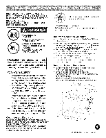
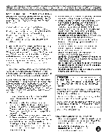
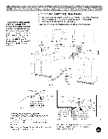
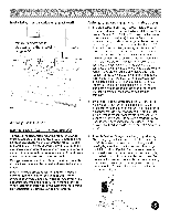
To eliminate the risk of burns or fire by reaching over heated surface units, cabinet storage space located above the surface units should be avoided, if cabinet storage is to be provided, the risk can be reduced by installing a range hood that projects horizontally a minimum of 5" beyond the bottom of the cabinets. Cabinet and countertop dimensions • Check for wall and cabinet clearances where the range will be installed. Check the stability of the floor where the range will be installed. Check for proper electrical and gas supply. Note: All dimensions provided are minimal unless otherwise stated. 18" Minimum on either side of 13" Maximum depth for cabinets above ramge top 30" Cabinet Opening width Back Wall Fig. A Fig. B Back Wall Install a flush mount 240V 40/50 ampere electrical wall outlet in the shaded area. Do not seal the range to side cabinets. Do not pinch the power supply cord between the range and the wall. If cabinet depth is greater than 25", the oven front frame must extend beyond cabinet front by 1/2" minimum. All openings in the wall or floor where the range is to be installed must be sealed. 11" Back Wall I This shaded floor area is for thru the floor connection of Add 1/2" NPT 90 ° Max. gas pipe stub and shut-off valve. black pipe elbow to the gas supply pipe stub and orient the Fig. C elbow as shown. Note: The gas supply pipe stube and elbow assembly centerline should not exceed 4" height form the floor.
-
 1
1 -
 2
2 -
 3
3 -
 4
4 -
 5
5 -
 6
6 -
 7
7 -
 8
8 -
 9
9 -
 10
10 -
11
-
12
 |
 |
