Kenmore 4812 Installation Instructions - Page 9
installations
 |
View all Kenmore 4812 manuals
Add to My Manuals
Save this manual to your list of manuals |
Page 9 highlights
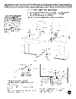
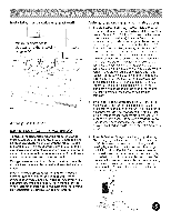
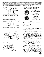
Range installations steps 2. (3 & 4 - Wire Permanent Connections) Strip insulation away from the ends of the permanent wiring for Line 1, Line 2, Neutral (also strip ground wire on 4Wire Connections). Tighten all 3 wire leads to the terminal block (Follow wire locations shown in Fig. 35). iMPORTANT NOTE; DO NOT LOOSEN the factory installed nut connections which secure the range wiring to the terminal block. Electrical failure or loss of electrical connection may occur if these 3 nuts are loosened or removed. NOTE: For 3=Wire Permanent Connections skip Steps 3 & 4 and continue with Step 5. 3. {4=Wire Permanent Connection ONLY) Disconnect the ground strap. Remove the factory installed ground screw & plate to release the factory installed copper ground strap from frame of the appliance. Cut and discard the copper strap from the terminal block. KEEP the ground screw, ground plate and go to Step 4. 4. (4-Wire Permanent Connection ONLY} Connectthe ground wire lead (Green) to the frame of the appliance using the ground screw & plate as shown in Fig. 36. Be sure to install using the same hole in the frame where the ground screw was originally installed. 5. (3 & 4 =Wire Permanent Connections} Make sure all connections are tightened securely and replace the rear access cover (See Fig. 30). GROUND SCREW ,tp= GROUND WIRE LEAD PROPER GROUND FOR 4-WIRE ND PERMANENT CONNECTION Fig. 36 FOR 3 & 4-Wire Permanent Connections ,_=Tighten all 3 wire leads Terminal block Line 2 plate Ground strap NOTE: Non-terminated field wire compression connections must be set at approximately 22in./Ibs. Always use 10 ga. wire or larger. Pressure Regulator Location and Installation of Gas Supply ) Flexible Appliance Conduit Pressure Regulator Flare Adaptor ..........A...daptor Shutoff Black Pipe Fig. 37 Off
-
 1
1 -
2
-
3
-
 4
4 -
 5
5 -
 6
6 -
 7
7 -
 8
8 -
 9
9 -
 10
10 -
 11
11 -
 12
12
 |
 |
