Kenmore 7748 Installation Instructions - Page 4
gas supply. - range
 |
View all Kenmore 7748 manuals
Add to My Manuals
Save this manual to your list of manuals |
Page 4 highlights
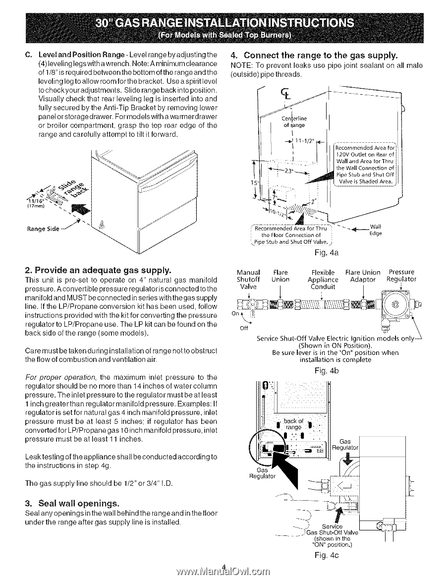
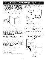
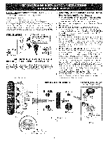
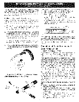
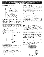
C= Level and Position Range- Level range by adjusting the (4) leveling legs with a wrench. Note: A minimum clearance of 1/8" is required between the bottom of the range and the leveling leg to allow room for the bracket. Use a spirit level to check your adjustments. Slide range back into position. Visually check that rear leveling leg is inserted into and fully secured by the Anti-Tip Bracket by removing lower panel or storage drawer. For models with a warmerdrawer or broiler compartment, grasp the top rear edge of the range and carefully attempt to tilt it forward. 4. Connect the range to the gas supply. NOTE: To prevent leaks use pipe joint sealant on all male (outside) pipe threads. _Recommended Area for 120V Outlet on Rear of Wall and Area for Thru the Wall Connection of Pipe Stub and Shut Off Valve is Shaded Area. (17rnrn) % Range Side / 2. Provide an adequate gas supply. This unit is pre-set to operate on 4" natural gas manifold pressure. A convertible pressure regulator is connected to the manifold and MUST be connected in series with the gas supply line. If the LP/Propane conversion kit has been used, follow instructions provided with the kit for converting the pressure regulator to LP/Propane use. The LP kit can be found on the back side of the range (some models). Care must be taken during installation of range not to obstruct the flow of combustion and ventilation air. For proper operation, the maximum inlet pressure to the regulator should be no more than 14 inches of water column pressure. The inlet pressure to the regulator must be at least 1 inch greater than regulator manifold pressure. Examples: If regulator is set for natural gas 4 inch manifold pressure, inlet pressure must be at least 5 inches; if regulator has been converted for LP/Propane gas 10 inch manifold pressure, inlet pressure must be at least 11 inches. Leak testing of the appliance shall be conducted according to the instructions in step 4g. The gas supply line should be 1/2" or 3/4" I.D. 3. Seal wall openings. Seal any openings in the wall behind the range and in the floor under the range after gas supply line is installed. Area for Thru the Floor Connection of Pipe Stub and Shut Off Valve. " __ Fig. 4a Wall Edge Manual Shutoff Valve Flare Union / Flexible Flare Union Pressure Appliance Adaptor Regulator Conduit _ Off Service Shut-Off Valve Electric Ignition _m,-Io_1d_els o_1n_l,y_ (Shown in ON Position). Be sure lever is in the "On" position when installation is complete Fig. 4b Service Shut-Off Valve (shown in the "ON" position.) Fig. 4c
-
 1
1 -
 2
2 -
 3
3 -
 4
4 -
 5
5 -
 6
6 -
 7
7 -
 8
8
 |
 |