Kenmore 7748 Installation Instructions - Page 6
F;oot, ofoookto
 |
View all Kenmore 7748 manuals
Add to My Manuals
Save this manual to your list of manuals |
Page 6 highlights
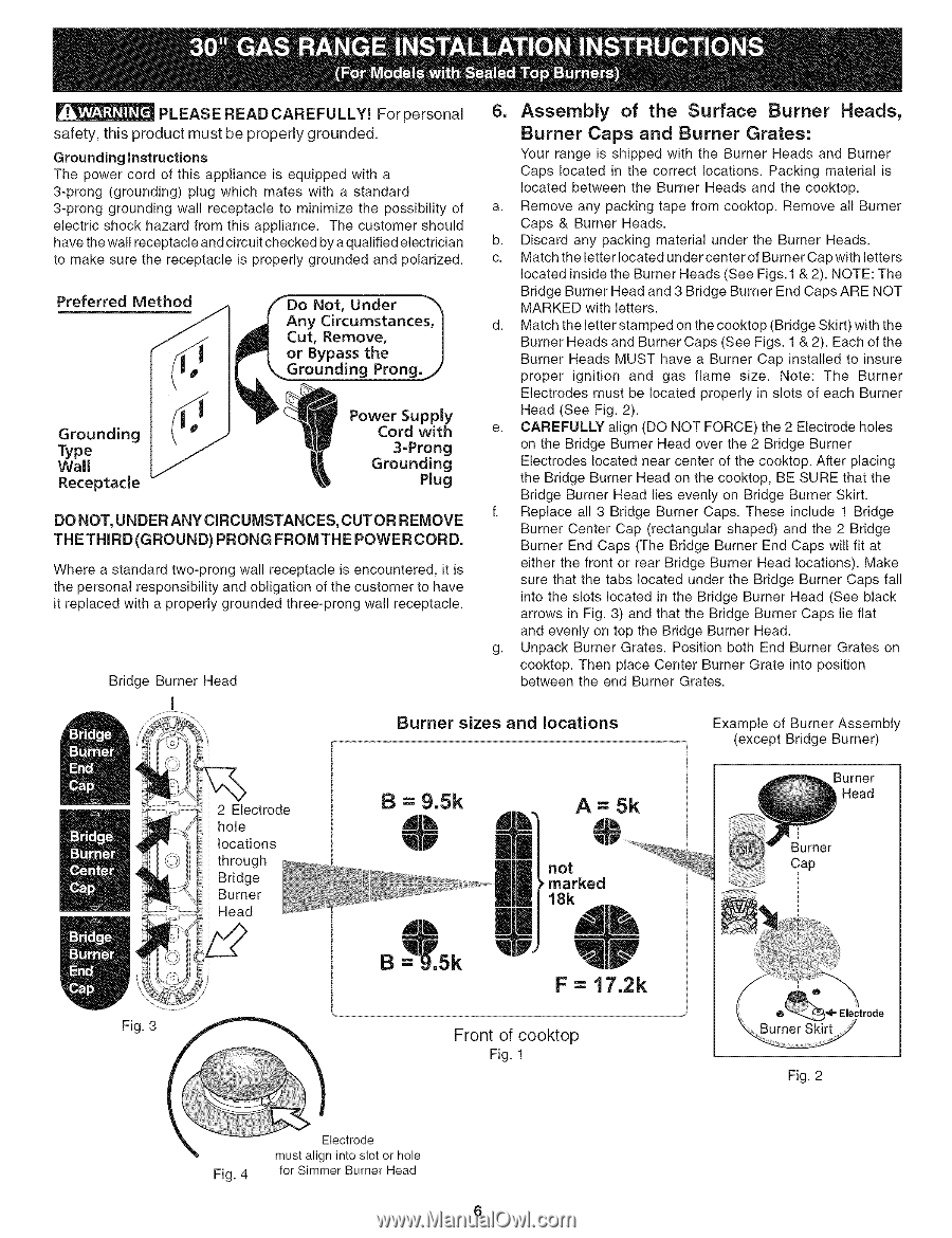
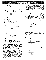
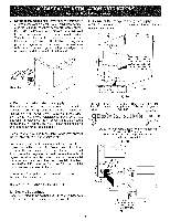
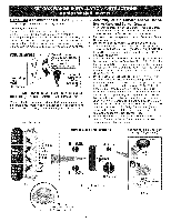
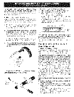
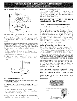
PLEASE READ CAREFULLY! For personal 6. Assembly of the Surface Burner Heads, safety, this product must be properly grounded. Burner Caps and Burner Grates: Grounding instructions The power cord of this appliance is equipped with a 3-prong (grounding) plug which mates with a standard 3-prong grounding wall receptacle to minimize the possibility of electric shock hazard from this appliance. The customer should have the wall receptacle and circuit checked by a qualified electrician to make sure the receptacle is properly grounded and polarized. Preferred Not, Under Your range is shipped with the Burner Heads and Burner Caps located in the correct locations. Packing material is located between the Burner Heads and the cooktop. a. Remove any packing tape from cooktop. Remove all Burner Caps & Burner Heads. b. Discard any packing material under the Burner Heads. c. Match the letter located under center of Burner Cap with letters located inside the Burner Heads (See Figs. 1 & 2). NOTE: The Bridge Burner Head and 3 Bridge Burner End Caps ARE NOT MARKED with letters. d. Match the letter stamped on the cooktop (Bridge Skirt) with the Burner Heads and Burner Caps (See Figs. 1 & 2). Each of the g Prong. Burner Heads MUST have a Burner Cap installed to insure proper ignition and gas flame size. Note: The Burner Grounding Type Wall Receptacle Power Supply Cord with 3=Prong Grounding Plug DO NOT, UNDER ANY CIRCUMSTANCES, CUT OR REMOVE THETHIRD(GROUND) PRONG FROMTHE POWER CORD. Electrodes must be located properly in slots of each Burner Head (See Fig. 2). e. CAREFULLY align (DO NOT FORCE) the 2 Electrode holes on the Bridge Burner Head over the 2 Bridge Burner Electrodes located near center of the cooktop. After placing the Bridge Burner Head on the cooktop, BE SURE that the Bridge Burner Head lies evenly on Bridge Burner Skirt. f. Replace all 3 Bridge Burner Caps. These include 1 Bridge Burner Center Cap (rectangular shaped) and the 2 Bridge Burner End Caps (The Bridge Burner End Caps will fit at Where a standard two-prong wall receptacle is encountered, it is the personal responsibility and obligation of the customer to have it replaced with a properly grounded three-prong wall receptacle. either the front or rear Bridge Burner Head locations). Make sure that the tabs located under the Bridge Burner Caps fall into the slots located in the Bridge Burner Head (See black arrows in Fig. 3) and that the Bridge Burner Caps lie flat and evenly on top the Bridge Burner Head. Bridge Burner Head g. Unpack Burner Grates. Position both End Burner Grates on cooktop. Then place Center Burner Grate into position between the end Burner Grates. I Burner sizes and locations Example of Burner Assembly (except Bridge Burner) 2 Electrode hole locations through Bridge Burner Head B=9.5k A=5k not _-marked 18k Burner Head Burner Cap F = 17.2k Fig. 3 F..;.o..o..t.fo..o..o..k..t.o Fig. 1 Fig. 2 Fig. 4 inclrOsdleotr hole for Simmer Burner Head
-
 1
1 -
 2
2 -
 3
3 -
 4
4 -
 5
5 -
 6
6 -
 7
7 -
 8
8
 |
 |