Kenmore 7972 Installation Instructions - Page 7
Electrical, Connections, For A 4-wire, System - washer
 |
UPC - 883049200989
View all Kenmore 7972 manuals
Add to My Manuals
Save this manual to your list of manuals |
Page 7 highlights
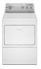
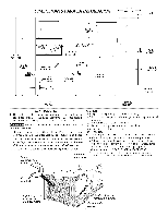
NON-CANADIAN ELECTRICLaundry Center 1. Remove the screw securing the terminal block access cover to the rear panel and remove cover. J INSTALLATION Run some water from the hot and cold faucets to flush the water lines and remove particles that might clog up the water valve screens. 2. Install a U.L approved strain relief connector in the entry hole on the back panel. 3. Remove the neutral ground wire from the green ground screw located above the termial block. . Check inlet hoses to ensure the rubber washers are installed in each end. 3. Carefully connect the inlet hoses to the water valve (on the left side of the washer cabinet), tighten by hand, then tighten another 2/3 turn with pliers. GREEN GROUND SCREW GREEN CONDUCTOR SILVER TERMINAL TERMINAL BLOCK NEUTRAL GROUNQ WIRE BLACK WHITE STRAIN RELIEF MOUNTING BRACKET, POWER CORD ELECTRICAL CONNECTIONS FOR A 4-WIRE SYSTEM 4. Insert a NEMA 14-30 Type ST or SRDT,U.L approved power cord through the strain relief. 5. Attach the green power cord ground wire to the cabinet with the green ground screw. 6. Attach the white (neutral) wire from the power cord and the neutral ground wire from the appliance harness to the silver colored center terminal on the terminal block. Tighten the screw securely. _ DO NOT CROSS THREAD OR OVERTIGHTEN THESE CONNECTIONS. 4. Determine which water faucet is the HOTwater faucet and carefully connect the bottom inlet hose to the HOTwater faucet, tighten by hand, then tighten another 2/3 turn with pliers. Carefully connect the top inlet hose to the COLD water faucet, tighten by hand, then tighten another 2/3 turn with pliers. DO NOT CROSS THREAD OR OVERTIGHTEN THESE CONNECTIONS. Turn the water on and check for leaks at both connections. . Carefully move the laundry center to its final location. 6. To ensure the laundry center is level and solid on all four legs, tilt the laundry center forward so the rear legs are off the ground. Gently set the laundry center back down to allow the rear legs to self adjust. Placea level on top of the washer. Check it side to side, then front to back. Screw the front leveling legs up or down to ensure the laundry center is resting solid on all four legs (no rocking of the laundry center should exist). NOTE: Keep the leg extension at a minimum to prevent excessive vibration. 7. GAS CONNECTION (Gas laundry centers only) a. Remove the shipping cap from gas pipe at the rear of the dryer. 7. Attach the red and black wires from the power cord to the outer brass-colored terminals on the terminal block. Tighten both screws securely. 8. Tighten the screws securing the cord restraint firmly against the power cord. 9. Reinstall the terminal block access cover. NOTE: DO NOT connect the laundry center to L.R gas service without converting the gas valve. An LR conversion kit must be installed by a qualified gas technician. b. Connect a 1/2 inch (1.27 cm) I.D. semi-rigid or approved pipe from the gas supply line to the 3/8 inch (0.96 cm) pipe located on the back of the dryer. Use a 1/2 inch (1.27 cm) to 3/8 inch (0.96 cm) reducer for the connection. Apply an approved thread sealer that is resistant to the corrosive action of liquefied gases on all pipe connections. c. Open the shutoff valve in the gas supply line. d. Test all connections by brushing on a soapy water solution. NEVER TEST FOR GAS LEAKS WITH AN OPEN FLAME.
-
 1
1 -
 2
2 -
 3
3 -
 4
4 -
 5
5 -
 6
6 -
 7
7 -
 8
8 -
 9
9 -
 10
10 -
 11
11 -
 12
12 -
13
-
14
-
15
-
16
 |
 |
