Kenmore 9802 Installation Instructions - Page 3
Silver, range, Ter, inal - white
 |
View all Kenmore 9802 manuals
Add to My Manuals
Save this manual to your list of manuals |
Page 3 highlights
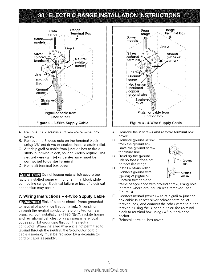
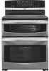
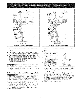
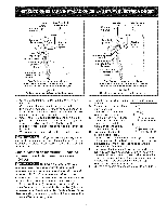
From range models .... Silver . colored._ termi_ Range ...........Term/ inal Box Line 2 ...... (Nwehuittreal or center) Line 1-4_ Ground link From Range range ..... Ter, inaBl o, models ...... Line 2 Silver / colored-(/ termi_ Line 1=_ Ground" screw No. 8 green insulated copper ground wire J eutral (white or _center) Figure 2 = 3=Wire Supply Cable A. Remove the 2 screws and remove terminal box cover. B. Remove the 3 loose nuts on the terminal block using 3/8" nut driver or socket. Install a strain relief. C. Attach pigtail or cable from junction box to the 3 studs in terminal block, as local codes require. The neutral wire (white) or center wire must be connected to center terminal. D. Reinstall terminal box cover, Do not loosen nuts which secure the factory installed range wiring to terminal block while connecting range. Electrical failure or loss of electrical connection may occur. 7. Wiring Instructions = 4-Wire Supply Cable Risk of electric shock, frame grounded to neutral of appliance through a link. Grounding through the neutral conductor is prohibited for new branch-circuit installations (1996 NEC); mobile homes; and recrational vehicles, or in an area where local codes prohibit grounding through the neutral conductor. When installed where it is not permitted to ground through the neutral, the 3-condutor cord or cable assembly must be replaced by a 4-conductor cord or cable assembly. Pigtail or from junction box Figure 3 =4-Wire Supply Cable A, Remove the 2 screws and remove terminal box cover. B. Remove ground screw from the ground link. Save the ground screw for future use. C, Bend up the ground link so that it does not contact the range, link D, Install a strain relief. Connect ground wire Ground (green) of pigtail or junction box cable to screw frame of appliance with ground screw, using hole in frame where ground link was removed (see Figure 3). E, Connect neutral (white) wire of pigtail or junction box cable to center silver colored terminal of terminal box, and connect the other wires to outer terminals using the 3 loose nuts on the terminal block to terminal box using 3/8" nut driver or socket. F, Reinstall terminal box cover. 3
-
 1
1 -
 2
2 -
 3
3 -
 4
4 -
 5
5 -
 6
6 -
 7
7 -
 8
8
 |
 |