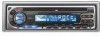
Kenwood KDC 205 Instruction Manual - Page 15
Installation
 |
UPC - 019048149879
View all Kenwood KDC 205 manuals
Add to My Manuals
Save this manual to your list of manuals |
Page 15 highlights
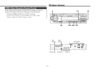
Installation ■ Installation Firewall or metal support Screw (M4X8) (commercially available) Self-tapping screw (commercially available) Metal mounting strap (commercially available) Bend the tabs of the mounting sleeve with a screwdriver or similar utensil and attach it in place. Make sure that the unit is installed securely in place. If the unit is unstable, it may malfunction (for example, the sound may skip). ■ Installing in Japanese-Made Cars 1 Refer to the section "Removing the hard rubber frame" (page 16) and then remove the hard rubber frame. 2 Align the holes in the unit (two locations on each side) with the vehicle mounting bracket and secure the unit with the accessory screws. T N N T T/N T: Toyota cars N: Nissan cars 3 ø5mm 8 mm MAX. 8mm MAX. 4 ø5mm Accessory3...for Nissan car Accessory4 ...for Toyota car • During installation, do not use any screws except for those provided. The use of different screws might result in damage to the main unit. • Damage may occur if a screwdriver or similar tool is used with excessive force during the installations. ■ Screwing the Faceplate on the Unit (KDC-205/205CR only) If you want to fasten the faceplate to the main unit so that it does not fall off, screw in the provided screw (ø4 X 16 mm) in the hole shown below. Accessory5 Never insert the taptite screw (ø4 × 16 mm) in any other screw hole than the one specified. If you screw it in another hole, it will contact and may cause damage to the mechanical parts inside the unit. - 15 -
-
 1
1 -
2
-
3
-
4
-
5
-
6
-
7
-
8
-
9
-
 10
10 -
 11
11 -
 12
12 -
 13
13 -
 14
14 -
 15
15 -
 16
16 -
 17
17 -
 18
18 -
 19
19 -
 20
20 -
21
-
22
-
23
-
24
-
25
-
26
-
27
-
28
-
29
-
30
-
31
-
32
-
33
-
34
-
35
-
36
-
37
-
38
-
39
-
40
-
41
-
42
-
43
-
44
-
45
-
46
-
47
-
48
-
49
-
50
-
51
-
52
-
53
-
54
-
55
-
56
-
57
-
58
-
59
-
60
-
61
-
62
-
63
-
64
-
65
-
66
-
67
-
68
-
69
-
70
-
71
-
72
-
73
-
74
-
75
-
76
 |
 |
