Kenwood KDC-X500 North America - Page 35
Part list for installation, Wiring connection
 |
View all Kenwood KDC-X500 manuals
Add to My Manuals
Save this manual to your list of manuals |
Page 35 highlights
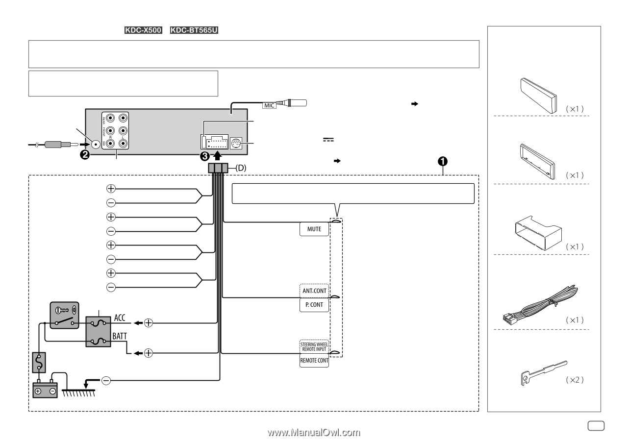
Wiring connection (for / ) IMPORTANT : We recommend installing the unit with a commercially available custom wiring harness specific for your car and leave this job to professionals for your safety. Consult your car audio dealer. When connecting to an external amplifier, connect its ground wire to the car's chassis to avoid damaging the unit. MIC (Microphone input terminal) ( 15) Antenna terminal Fuse (10 A) Rear/ front/ subwoofer output Expansion port (12 V 500 mA) To the optional SiriusXM Vehicle Tuner (commercially available) ( 12) To front speaker (left) To front speaker (right) To rear speaker (left) To rear speaker (right) Ignition switch Car fuse box White White/Black Gray Gray/Black Green Green/Black Purple Purple/Black Red (Ignition wire) Car fuse box Yellow (Battery wire) Black (Ground wire) If no connections are made, do not let the wire come out from the tab. Brown (Mute control wire) To connect the Kenwood navigation system, refer your navigations manual Blue/White (Power control wire/ Antenna control wire) Light blue/yellow (Steering remote control wire) To the power control terminal when using the optional power amplifier or to the antenna control terminal in the vehicle To the steering wheel remote control adapter Battery To the metallic body or chassis of the car Part list for installation (A) Faceplate (B) Trim plate (C) Mounting sleeve (D) Wiring harness (E) Extraction key ENGLISH 31
-
 1
1 -
2
-
3
-
4
-
5
-
6
-
7
-
8
-
9
-
10
-
11
-
12
-
13
-
14
-
15
-
16
-
17
-
18
-
19
-
20
-
21
-
22
-
23
-
24
-
25
-
26
-
27
-
28
-
29
-
 30
30 -
 31
31 -
 32
32 -
 33
33 -
 34
34 -
 35
35 -
 36
36 -
 37
37 -
 38
38 -
 39
39 -
 40
40 -
41
-
42
-
43
-
44
-
45
-
46
-
47
-
48
-
49
-
50
-
51
-
52
-
53
-
54
-
55
-
56
-
57
-
58
-
59
-
60
-
61
-
62
-
63
-
64
-
65
-
66
-
67
-
68
-
69
-
70
-
71
-
72
-
73
-
74
-
75
-
76
-
77
-
78
-
79
-
80
-
81
-
82
-
83
-
84
-
85
-
86
-
87
-
88
-
89
-
90
-
91
-
92
-
93
-
94
-
95
-
96
-
97
-
98
-
99
-
100
-
101
-
102
-
103
-
104
 |
 |