Kenwood TM-271A User Manual - Page 13
Arket, Odels
 |
View all Kenwood TM-271A manuals
Add to My Manuals
Save this manual to your list of manuals |
Page 13 highlights
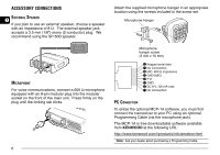
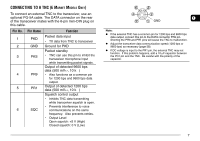
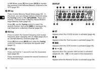
CONNECTING TO A TNC (E MARKET MODELS ONLY) To connect an external TNC to the transceiver, use an optional PG-5A cable. The DATA connector on the rear of the transceiver mates with the 6-pin mini-DIN plug on this cable. Pin No. 1 2 3 4 5 6 Pin Name PKD GND PKS PR9 PR1 SQC Function Packet data input • TX data from TNC to transceiver Ground for PKD Packet standby • TNC can use this pin to inhibit the transceiver microphone input while transmitting packet signals. Output of detected 9600 bps data (500 mVP-P, 10 k ) • Also functions as a common pin for 1200 bps and 9600 bps data output. Output of detected 1200 bps data (500 mVP-P, 10 k ) Squelch control output • Inhibits TNC data transmitting while transceiver squelch is open. • Prevents interference to voice communications on the same frequency. Also prevents retries. • Output Level Open squelch: +5 V (High) Closed squelch: 0 V (Low) 1 GND Note: ◆ If the external TNC has a common pin for 1200 bps and 9600 bps data output, connect this pin to the DATA connector PR9 pin. Shorting the PR9 and PR1 pins will cause the TNC to malfunction. ◆ Adjust the transceiver data communication speed (1200 bps or 9600 bps) as necessary {page 58}. ◆ If DC voltage is input to the PR1 pin, the external TNC may not function. If this problem happens, add a 10 µF capacitor between the PR1 pin and the TNC. Be careful with the polarity of the capacitor. 7
-
 1
1 -
2
-
3
-
4
-
5
-
6
-
7
-
 8
8 -
 9
9 -
 10
10 -
 11
11 -
 12
12 -
 13
13 -
 14
14 -
 15
15 -
 16
16 -
 17
17 -
 18
18 -
19
-
20
-
21
-
22
-
23
-
24
-
25
-
26
-
27
-
28
-
29
-
30
-
31
-
32
-
33
-
34
-
35
-
36
-
37
-
38
-
39
-
40
-
41
-
42
-
43
-
44
-
45
-
46
-
47
-
48
-
49
-
50
-
51
-
52
-
53
-
54
-
55
-
56
-
57
-
58
-
59
-
60
-
61
-
62
-
63
-
64
-
65
-
66
-
67
-
68
-
69
-
70
-
71
-
72
-
73
-
74
-
75
-
76
-
77
-
78
-
79
-
80
 |
 |
