Kenwood VR-9050 Instruction Manual - Page 13
Digital connections
 |
View all Kenwood VR-9050 manuals
Add to My Manuals
Save this manual to your list of manuals |
Page 13 highlights
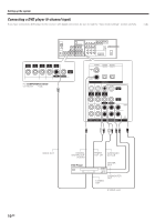
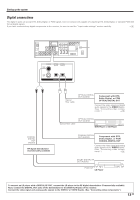
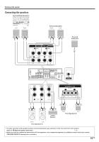
Setting up the system Digital connections The digital in jacks can accept DTS, Dolby Digital, or PCM signals. Connect components capable of outputting DTS, Dolby Digital, or standard PCM (CD) format digital signals. If you have connected any digital components to the receiver, be sure to read the "Input mode settings" section carefully. 8 COAXIAL VIDEO 2 OPTICAL OPTICAL CD/DVD VIDEO 3 DVD/ 6CH DIGITAL IN COAXIAL DIGITAL OUT (AUDIO) RF digital demodulator (Commercially available) Optical fiber cable OPTICAL DIGITAL OUT (AUDIO) Component with DTS, Dolby Digital, or PCM OPTICAL DIGITAL OUT Connect the video signal and digital audio signals to the VIDEO 3 jacks. (See "Connecting video compo- nents".) @ Optical fiber cable OPTICAL DIGITAL OUT (AUDIO) DVD Player or CD Player COAXIAL DIGITAL OUT (AUDIO) Component with DTS, Dolby Digital, or PCM COAXIAL DIGITAL OUT Connect the video signal and analog audio signals to the VIDEO 2 jacks. (See "Connecting video compo- nents".) @ DOLBY DIGITAL RF OUT (AUDIO) PCM OUT LD Player To connect an LD player with a DIGITAL RF OUT, connect the LD player to the RF digital demodulator (Commercially available). Next, connect the DIGITAL OUT jacks of the demodulator to the DIGITAL IN jacks of the receiver. Connect the video signal and analog audio signals to the VIDEO 2 or VIDEO 3 jacks. (See "Connecting video components".) 13 EN
-
 1
1 -
2
-
3
-
4
-
5
-
6
-
7
-
 8
8 -
 9
9 -
 10
10 -
 11
11 -
 12
12 -
 13
13 -
 14
14 -
 15
15 -
 16
16 -
 17
17 -
 18
18 -
19
-
20
-
21
-
22
-
23
-
24
-
25
-
26
-
27
-
28
-
29
-
30
-
31
-
32
-
33
-
34
-
35
-
36
 |
 |
