Kenwood XXV-02A Instruction Manual - Page 5
Controls - 4 channel amplifier
 |
UPC - 019048160621
View all Kenwood XXV-02A manuals
Add to My Manuals
Save this manual to your list of manuals |
Page 5 highlights
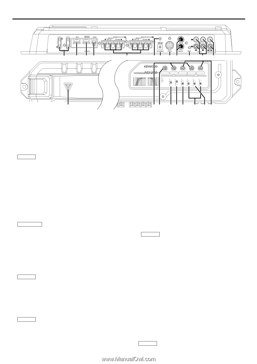
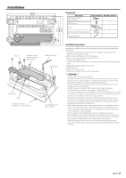
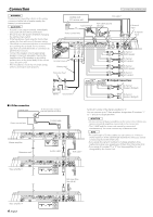
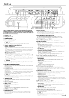
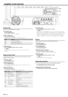
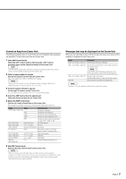
Controls 78 30 30 1 2 34 456 23 9 01 5 67 8 9 0 !@ 150 100 70 50 200 LPF FREQUENCY(Hz) 100 1 100 1 70 50 150 2 3 4 200 (MIN)5 0.5 70 0.3 0.2(MAX) 50 150 2 3 4 200 (MIN)5 0.5 0.3 0.2(MAX) HPF INPUT HPF INPUT FREQUENCY(Hz) SENSITIVITY(V) FREQUENCY(Hz) SENSITIVITY(V) HPF OPERATION LPF OPERATION 0 0 -4 -4 -8 -8 -12 -12 -16 -16 -20 -20 30 50 100 200 400 1K (Hz) 30 50 100 200 400 1K (Hz) 200 Hz 150 Hz 100 Hz 70 Hz 50 Hz B ch FILTER AMP CONT HPF ON A ch ISF OPERATION HPF OPERATION ON MONO(Lch) ON MONO(Lch) OFF LPF OFF OFF STEREO OFF STEREO # This is a 4 channel amplifier including 2 stereo amplifiers in a body. One amplifier is referred to as amplifier A and the other is amplifier B. This unit is compatible with a large variety of systems by combining the switches and functions described in the following. 1 Fuse (30 A × 2) 2 Battery terminal 3 Ground terminal 4 Power control terminal Controls the unit ON/OFF. NOTE Controls the unit power. Be sure to connect it with all the systems. 5 Speaker output terminals (A.ch/B.ch) • Stereo Connections: When you wish to use the unit as a stereo amplifier, stereo connections are used. The speakers to be connected should have an impedance of 2Ω or greater. When multiple speakers are to be connected, ensure that the combined impedance is 2Ω or greater for each channel. • Bridged Connections: When you wish to use the unit as a high-output monaural amplifier, bridged connections are used. (Make connections to the LEFT channel 9 and the RIGHT channel · SPEAKER OUTPUT terminals.) The speakers to be connected should have an impedance of 4Ω or greater. When multiple speakers are to be connected, ensure that the combined impedance is 4Ω or greater. 2CAUTION The rated input of the speakers should be no less than the maximum output of the amplifier. Otherwise malfunction may result. 6 RCA cable ground lead terminal When using an RCA cable with a ground lead attached, connect the ground lead to this terminal. 7 ID NUMBER switch Sets an amp identification number (ID) to be used for amplifier control from the Center Unit. Assign ID Number "0" to an amplifier when you use it as the Master amplifier. Assign ID Numbers "1" to "7" to amplifiers when you use them as Slave amplifiers. Do not duplicate these numbers. NOTE After you have changed ID numbers of amplifiers, turn Off the POWER switch of the Center Unit and turn it On again. 8 TO H/U terminal After you have set the Master amplifier, connect it to the Center Unit. 9 REMOTE terminals Used to connect to Slave amplifiers. 0 RESET button Resets the microprocessor of the unit. NOTE The values you have set with the Amplifier Control are NOT reset. ! LINE IN terminal (A.ch/B.ch) @ LINE OUT terminal These jacks output respectively the signals input to amplifiers A and B. They always output the stereo signals regardless of the position of the OPERATION switch. 1 # Power indicator Lights when the POWER switch is turned On. The indicator flashes several seconds when the POWER switch is turned On or when the Protection function is activated. $ HPF FREQUENCY control (A.ch/B.ch) A: Sets the cutoff frequency when the "HPF" switch is set to "ON". B: Sets the cutoff frequency when the "FILTER" switch is set to "HPF". % LPF FREQUENCY control (B.ch) Sets the cutoff frequency when the "FILTER" switch is set to "LPF". ^ FILTER switch (B.ch) This switch allows to apply high-pass or low-pass filtering to the speaker outputs. • HPF (High-Pass Filter) position: The filter outputs the band of higher frequencies than the frequency set with the "HPF FREQUENCY" control. • OFF position: The entire bandwidth is output without filtering. • LPF (Low-Pass Filter) position: The filter outputs the band of lower frequencies than the frequency set with the "LPF FREQUENCY" control. The speaker output is automatically switched to monaural (L+R). & AMP CONT (amplifier control) switch (B.ch) Used to bypass the circuit when you do not control the sound with the Amplifier Control. • ON position: You can control the sound of amplifier B using the Amplifier Control. • OFF position: Bypasses the Amplifier Control circuit. NOTE Amplifier control is possible even while OFF. * ISF (infrasonic filter) switch (B.ch) When this switch is "ON", the frequencies which are below the audible range and therefore inaudible are cut off so that the quality of the audible frequencies can be improved. ( OPERATION switch (A.ch/B.ch) The amplification methods of the signals input to amplifiers A and B can be selected independently according to the setting of this switch. • STEREO position: The amplifier can be used as a stereo amplifier. • MONO (Lch) position: Amplifies the signal input from the left side only. Set to this position and make bridged connections to use as a high-power monaural amplifier. (The input right signal is not output.) ) HPF (High-Pass Filter) switch (A.ch) This switch allows to apply high-pass filtering to the speaker outputs. • ON position: The filter outputs the band of higher frequencies than the frequency set with the "HPF FREQUENCY" control. • OFF position: The entire bandwidth is output without filtering. @1 INPUT SENSITIVITY control (A.ch/B.ch) Set this control according to the pre-output level of the center unit connected with this unit. NOTE For the pre-output level, refer to the in the instruction manual of the center unit. English 5
-
 1
1 -
 2
2 -
 3
3 -
 4
4 -
 5
5 -
 6
6 -
 7
7 -
 8
8 -
 9
9 -
 10
10 -
 11
11 -
12
-
13
-
14
-
15
-
16
-
17
-
18
-
19
-
20
-
21
-
22
-
23
-
24
-
25
-
26
-
27
-
28
 |
 |