KitchenAid KDRS462VSS Installation Guide - Page 11
Install Optional Backguard, Install Anti-Tip Bracket
 |
UPC - 883049155692
View all KitchenAid KDRS462VSS manuals
Add to My Manuals
Save this manual to your list of manuals |
Page 11 highlights
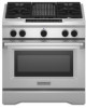
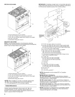
Install Optional Backguard All ranges may require a backguard. See "Cabinet Dimensions" in the "Location Requirements" section. See the "Tools and Parts" section for information on ordering. Remove island trim and attach backguard using 6 screws, insert 3 from the front and 3 from the back (9" [22.9 cm] backguard is shown). Measurement C: Optional distance from backwall. If backwall is constructed of a combustible material and a backguard is not installed, a 6" (15.2 cm) minimum clearance is required for all models. Install anti-tip bracket accordingly. A Install Anti-Tip Bracket WARNING B C A. Centerline B. Centerline of cutout to centerline of anti-tip bracket C. Backwall to back of range 3. Drill two ¹⁄₈" (3.0 mm) holes that correspond to the bracket holes of the determined mounting method. See the following. Floor Mounting B A Tip Over Hazard A child or adult can tip the range and be killed. Connect anti-tip bracket to rear range foot. Reconnect the anti-tip bracket, if the range is moved. Failure to follow these instructions can result in death or serious burns to children and adults. 1. Determine which mounting method to use: floor or wall. If you have a stone or masonry floor, you can use the wall mounting method. 2. Determine and mark centerline of the cutout space. The mounting bracket must be installed on the right side of the cutout. Position mounting bracket in cutout as shown in the following illustration. Measurement B: 30" (76.2 cm) ranges: 11⁵⁄₈" (29.5 cm) 36" (91.4 cm) ranges: 14⁵⁄₈" (37.1 cm) 48" (121.9 cm) ranges: 20⁵⁄₈" (52.4 cm) Wall Mounting B A. #12 x 1⁵⁄₈" screws B. Anti-tip bracket A A. #12 x 1⁵⁄₈" screws B. Anti-tip bracket 4. Using a Phillips screwdriver, mount anti-tip bracket to the wall or floor with the two #12 x 1⁵⁄₈" screws provided. Depending on the thickness of your flooring, longer screws may be necessary to anchor the bracket to the subfloor. Longer screws are available from your local hardware store. 5. Move range close enough to opening to allow for electrical connections to be made. Remove shipping base, cardboard or hardboard from under range. 6. Continue installing your range using the following installation instructions. 11
-
 1
1 -
2
-
3
-
4
-
5
-
 6
6 -
 7
7 -
 8
8 -
 9
9 -
 10
10 -
 11
11 -
 12
12 -
 13
13 -
 14
14 -
 15
15 -
 16
16 -
17
-
18
-
19
-
20
-
21
-
22
-
23
-
24
-
25
-
26
-
27
-
28
-
29
-
30
-
31
-
32
-
33
-
34
-
35
-
36
-
37
-
38
-
39
-
40
-
41
-
42
-
43
-
44
-
45
-
46
-
47
-
48
-
49
-
50
-
51
-
52
-
53
-
54
-
55
-
56
 |
 |
