KitchenAid KUID508HPS Installation Instructions - Page 9
If Ice Maker Is Currently Installed, Drain Pump Installation
 |
View all KitchenAid KUID508HPS manuals
Add to My Manuals
Save this manual to your list of manuals |
Page 9 highlights
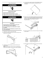
If Ice Maker Is Currently Installed NOTE: If ice maker is not installed, please proceed to "Drain Pump Installation" section. 1. Push the selector switch to the OFF position. WARNING Electrical Shock Hazard Disconnect power before servicing. Replace all parts and panels before operating. Failure to do so can result in death or electrical shock. 2. Unplug ice maker or disconnect power. 3. Turn off water supply. Wait 5 to 10 minutes for the ice to fall into the storage bin. Remove all ice from bin. 4. Unscrew the drain cap from the bottom of the water pan located inside the storage bin. Allow water to drain completely. Replace drain cap. See "Drain Cap" illustration. Drain Cap A A. Drain cap 5. If ice maker is built into cabinets, pull ice maker out of the opening. 6. Disconnect water supply line. See "Water Supply Line" illustration. Water Supply Line A B C B D C E A. 1/4" copper tubing B. Cable clamp C. 1/4" compression nut D. Ferrule (sleeve) E. Ice maker connection Drain Pump Installation NOTE: Do not kink, smash or damage tubes or wires during installation. 1. Unplug ice maker or disconnect power. 2. Remove rear panel. See "Rear Panel" illustration for screw locations. Pull rear panel away from the drain tube. For standard model discard the rear panel. For Custom panel model, set aside the rear panel (it will be reused in step 17). Rear Panel A B A A. Screw locations for standard model B. Screw locations for custom panel model 3. Remove the old drain tube and clamp attached to the ice maker bin. NOTE: Discard old drain tube and clamp. 4. Slide drain pump into the ice maker base on the right side. The pump mounting tab should slip into the rectangular slot in the ice maker base. It will be necessary to tip the pump slightly to slip into the slot. See "Drain Pump Mounting Tab Slot" illustration. Drain Pump Mounting Tab Slot A A. Mounting tab slot Drain Pump Installed A A. Drain pump installed 9
-
 1
1 -
2
-
3
-
 4
4 -
 5
5 -
 6
6 -
 7
7 -
 8
8 -
 9
9 -
 10
10 -
 11
11 -
 12
12 -
 13
13 -
 14
14 -
15
-
16
-
17
-
18
-
19
-
20
-
21
-
22
-
23
-
24
-
25
-
26
-
27
-
28
-
29
-
30
-
31
-
32
-
33
-
34
-
35
-
36
-
37
-
38
-
39
-
40
-
41
-
42
-
43
-
44
-
45
-
46
-
47
-
48
-
49
-
50
-
51
-
52
-
53
-
54
-
55
-
56
 |
 |
