LG 22MP57HQ-P Owners Manual - English - Page 13
Mounting on a wall
 |
View all LG 22MP57HQ-P manuals
Add to My Manuals
Save this manual to your list of manuals |
Page 13 highlights
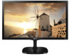
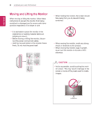
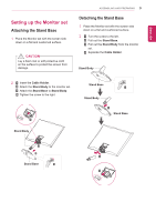
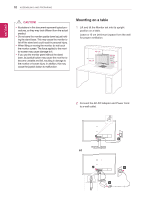
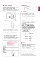
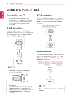
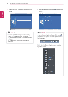
ASSEMBLING AND PREPARING 13 ENEGNLGISH Mounting on a wall For proper ventilation, allow a clearance of 10 cm on each side and from the wall. Detailed instructions are available from your dealer, see the optional Tilt Wall Mounting Bracket Installation and Setup Guide. 10 cm 10 cm 10 cm 10 cm If you intend to mount the Monitor set to a wall, attach Wall mounting interface (optional parts) to the back of the set. When you install the Monitor set using a wall mounting interface (optional parts), attach it carefully so it will not drop. 1 If you use screw longer than standard, the monitor might be damaged internally. 2 If you use improper screw, the product might be damaged and drop from mounted position. In this case, LG Electronics is not responsible for it. Model 22MP57A 23MP57A 24MP57D 22MP57D 23MP57D 24MP57HQ 22MP57HQ 23MP57H 24MP57VQ 22MP57VQ 23MP57HQ 27MP57HQ 23MP57VQ 27MP57VQ 27MP57HT Wall Mount (A x B) Standard screw Number of screws Wall Mount Plate (Optional) 75 x 75 M4 x L10 4 RW120 yyWall Mount (A x B) AB CAUTION yyDisconnect the power cord first, and then move or install the Monitor set. Otherwise electric shock may occur. yyIf you install the Monitor set on a ceiling or slanted wall, it may fall and result in severe injury. yyUse only an authorized LG wall mount and contact the local dealer or qualified personnel. yyDo not over tighten the screws as this may cause damage to the Monitor set and void your warranty. yyUse only screws and wall mounts that meet the VESA standard. Any damages or injuries by misuse or using an improper accessory are not covered by the warranty. yyScrew length from outer surface of back cover should be under 8mm. Wall mount Pad Back Cover Wall mount Pad Back Cover Standard screw Max.8mm NOTE yyUse the screws that are listed on the VESA standard screw specifications. yyThe wall mount kit will include an installation manual and necessary parts. yyThe wall mount bracket is optional. You can obtain additional accessories from your local dealer. yyThe length of screws may differ depending on the wall mount. Be sure to use the proper length. yyFor more information, refer to the instructions supplied with the wall mount.
-
 1
1 -
2
-
3
-
4
-
5
-
6
-
7
-
 8
8 -
 9
9 -
 10
10 -
 11
11 -
 12
12 -
 13
13 -
 14
14 -
 15
15 -
 16
16 -
 17
17 -
 18
18 -
19
-
20
-
21
-
22
-
23
-
24
-
25
-
26
-
27
-
28
-
29
-
30
-
31
-
32
-
33
-
34
-
35
-
36
-
37
-
38
-
39
-
40
-
41
-
42
 |
 |