LG 29FX4BL-LG Owner's Manual - Page 24
Connection of external equipment some models
 |
View all LG 29FX4BL-LG manuals
Add to My Manuals
Save this manual to your list of manuals |
Page 24 highlights
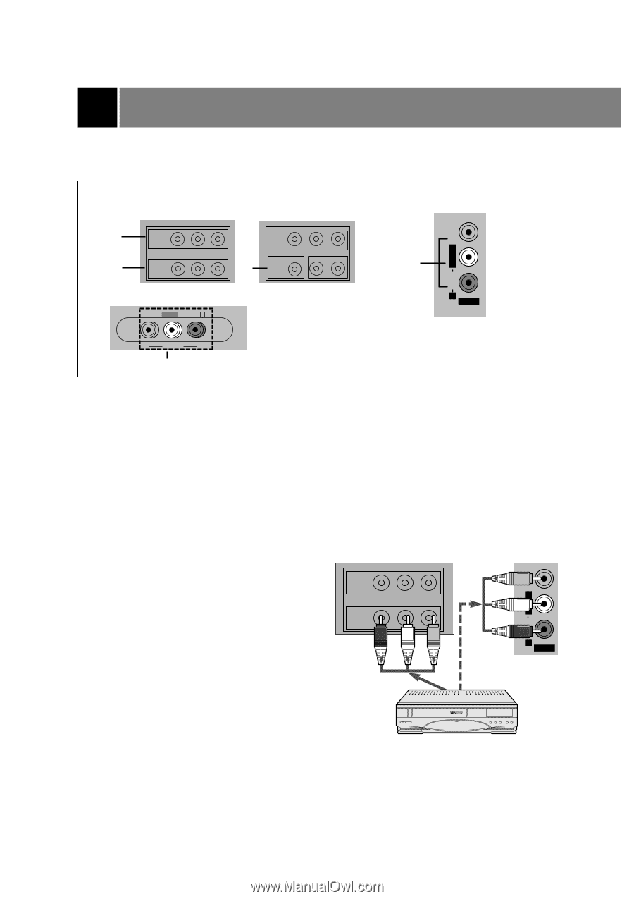
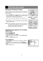
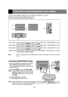
Connection of external equipment (some models) You can connect additional equipment, such as VCRs, camcorders etc. to your set. Here shown may be somewhat different from your set. These are an example drawing of typical jack layout. VIDEO L/MONO AUDIO R 4 OUT COMPONENT Y PB PR DVD IN(480i) VIDEO(L/MONO)AUDIO(R) 1 IN1 VIDEO (L/MONO) AUDIO(R) 2 IN2 3 VIDEO L/MONO AUDIO R AV IN 3 AV IN 3 3 1. IN 1 JACKS : Connect external equipment outputs (VCR, LASER DISC, CAMCORDER) to these inputs. Press the TV/VIDEO button to select AV1. 2. IN 2 JACKS : Connect external equipment outputs (VCR, LASER DISC, CAMCORDER) to these inputs. Press the TV/VIDEO button to select AV2. 3. IN 3 JACKS : Connect external equipment outputs (VCR, LASER DISC, CAMCORDER) to these inputs. Press the TV/VIDEO button to select AV3. 4. OUT JACKS: Connect external equipment inputs (VCR, Audio amplifier) to these outputs for recording or monitering the selected program. Note: This TV is programmed to remember which mode it was last set to, even if you turn the TV off. VIDEO L/MONO AUDIO R Connecting AUDIO/VIDEO IN Jacks 1. Connect the audio/video output jacks of the VCR to IN 1 or IN 2(A/V) jacks on the side or back of TV. If you connect the audio jack only, you can't hear the sound from the TV. OUT VIDEO(L/MONO)AUDIO(R) IN1 2. Press the TV/VIDEO button to select AV1 or AV2. Note: In some stereo models, if you connect the audio/video output jacks of the VCR to the AV AV IN 3(A/V) jacks on the front or side of TV, select AV3. < TV > AV IN 3 < TV > 3. Press the PLAY button on the VCR. The video playback is on the TV screen. < Playback VCR > Note: In case of MONO VCR, connect the output jack of VCR to the AUDIO L/MONO IN jack of TV so that the sound can be heard from both speakers. If you connect it to the AUDIO R IN jack of TV the sound is heard only from right speaker. 24
-
 1
1 -
2
-
3
-
4
-
5
-
6
-
7
-
8
-
9
-
10
-
11
-
12
-
13
-
14
-
15
-
16
-
17
-
18
-
 19
19 -
 20
20 -
 21
21 -
 22
22 -
 23
23 -
 24
24 -
 25
25 -
 26
26 -
 27
27 -
 28
28
 |
 |