LG 42LB1DRA Service Manual - Page 14
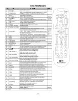
Cable Operation Confirmation, POWER PCB Assy Voltage, Adjustment, EDIDThe Extended Display, - no picture
 |
UPC - 719192169753
View all LG 42LB1DRA manuals
Add to My Manuals
Save this manual to your list of manuals |
Page 14 highlights
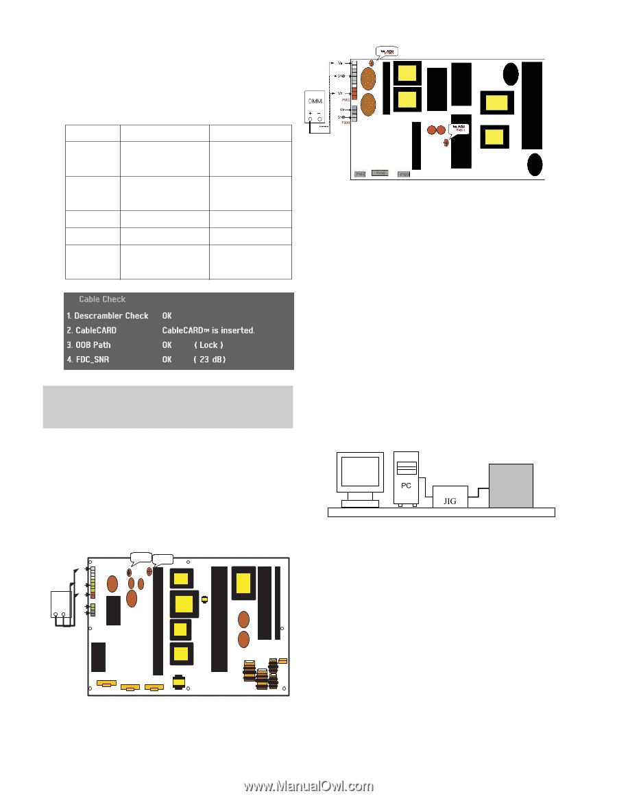
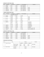
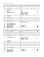
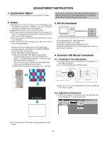
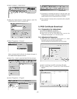
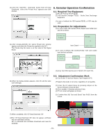
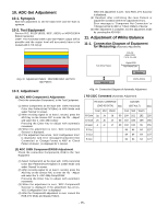
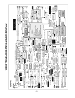
7. Cable Operation Confirmation (1) Confirm that the Cable Card is inserted in the slot. (2) Enter the EZ adjust menu by pressing the Adjust key on the Service Remote Control (S R/C). (3) Go to number 2 Cable Check and press the Right key (G ) . (4) Confirm items below. Name Descrambler Check CableCARD OOB Path FDC_SNR Video Signal Normal OK Defective Not OK CableCARDTM is inserted. OK(Lock) OK(20dB above) Normal Screen CableCARDTM is removed. Not OK(Unlock) Not OK(20dB under) Black Screen (No Picture) Each PCB Assy must be checked by Check JIG Set before assembly. (Especially, be careful Power PCB Assy which can cause Damage to the PDP Module.) Connection Diagram of Power Adjustment for Measuring (Power Board): 60" 9. EDID(The Extended Display Identification Data)/DDC (Display Data Channel) Download This is the function that enables "Plug and Play". 9-1. HDMI EDID Data Input (1) Required Test Equipment 1) PC, Jig for adjusting DDC. (PC serial to D-sub Connection equipment) 2) S/W for writing DDC(EDID data write & read) 3) D-Sub cable 4) Jig for HDMI Cable connection (2) Preparation for Adjustments & Setting of Device 1) Set devices as below and turn on the PC and JIG. 2) Open S/W for writing DDC (EDID data write & read). (operated in DOS mode) 8. POWER PCB Assy Voltage Adjustment (Va, Vs Voltage Adjustment) 8-1. Test Equipment : D.M.M 1EA 8-2. Connection Diagram for Measuring Refer to Fig 1. Vs DMM + - GND Va GND 5V P805 P804 VR 95 Vs AD Va AD VR90 PDP TV SET (or Digital Board) CN1 P800 1 P803 P802 1 1 Connection Diagram of Power Adjustment for Measuring (Power Board): 50" - 14 -
-
 1
1 -
2
-
3
-
4
-
5
-
6
-
7
-
8
-
 9
9 -
 10
10 -
 11
11 -
 12
12 -
 13
13 -
 14
14 -
 15
15 -
 16
16 -
 17
17 -
 18
18 -
 19
19 -
20
-
21
-
22
-
23
-
24
-
25
-
26
-
27
-
28
-
29
-
30
-
31
-
32
-
33
-
34
-
35
-
36
-
37
-
38
-
39
-
40
-
41
-
42
-
43
-
44
-
45
-
46
-
47
-
48
-
49
-
50
-
51
-
52
-
53
-
54
-
55
-
56
-
57
-
58
-
59
-
60
-
61
-
62
-
63
-
64
-
65
-
66
-
67
-
68
-
69
-
70
-
71
-
72
-
73
-
74
-
75
-
76
-
77
-
78
-
79
-
80
-
81
 |
 |