LG DH65EL Service Manual - Page 14
Control, Parts
 |
View all LG DH65EL manuals
Add to My Manuals
Save this manual to your list of manuals |
Page 14 highlights
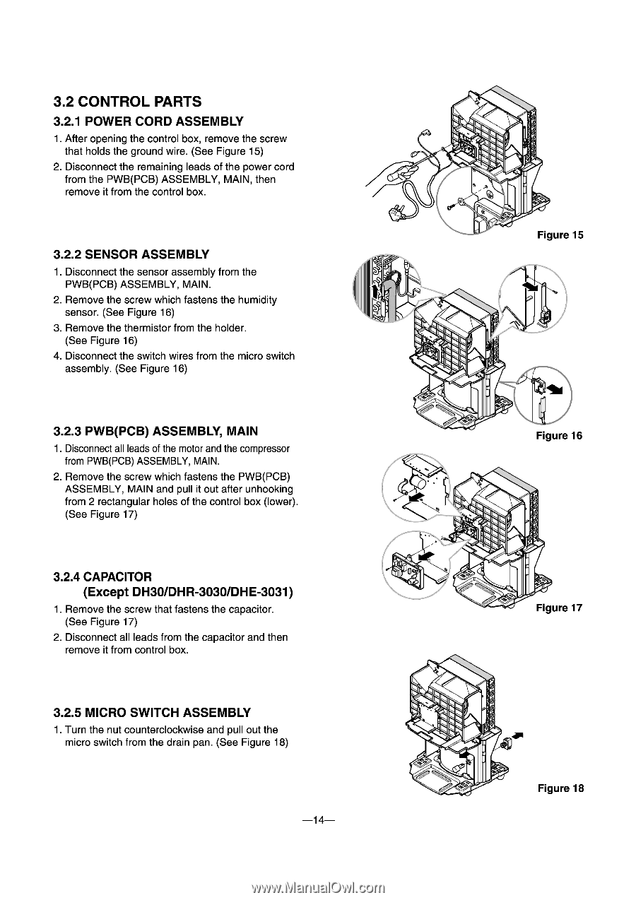
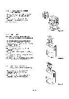
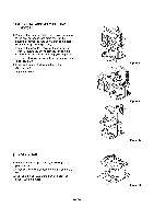
3.2 CONTROL PARTS 3.2.1 POWER CORD ASSEMBLY 1. After opening the control box, remove the screw that holds the ground wire. (See Figure 15) 2. Disconnect the remaining leads of the power cord from the PWB(PCB) ASSEMBLY, MAIN, then remove it from the control box. 3.2.2 SENSOR ASSEMBLY 1. Disconnect the sensor assembly from the PWB(PCB) ASSEMBLY, MAIN. 2. Remove the screw which fastens the humidity sensor. (See Figure 16) 3. Remove the thermistor from the holder. (See Figure 16) 4. Disconnect the switch wires from the micro switch assembly. (See Figure 16) 3.2.3 PWB(PCB) ASSEMBLY, MAIN 1. Disconnect all leads of the motor and the compressor from PWB(PCB) ASSEMBLY, MAIN. 2. Remove the screw which fastens the PWB(PCB) ASSEMBLY, MAIN and pull it out after unhooking from 2 rectangular holes of the control box (lower). (See Figure 17) 3.2.4 CAPACITOR (Except DH30/DHR-3030/DHE-3031) 1. Remove the screw that fastens the capacitor. (See Figure 17) 2. Disconnect all leads from the capacitor and then remove it from control box. 3.2.5 MICRO SWITCH ASSEMBLY 1. Turn the nut counterclockwise and pull out the micro switch from the drain pan. (See Figure 18) -14- Figure 15 4% I Figure 16 • 0 Figure 17 Figure 18
-
 1
1 -
2
-
3
-
4
-
5
-
6
-
7
-
8
-
 9
9 -
 10
10 -
 11
11 -
 12
12 -
 13
13 -
 14
14 -
 15
15 -
 16
16 -
 17
17 -
 18
18 -
 19
19 -
20
-
21
-
22
-
23
-
24
 |
 |