LG DLE9577SM Owners Manual - Page 13
Connecting the Exhaust, and Venting System.
 |
View all LG DLE9577SM manuals
Add to My Manuals
Save this manual to your list of manuals |
Page 13 highlights
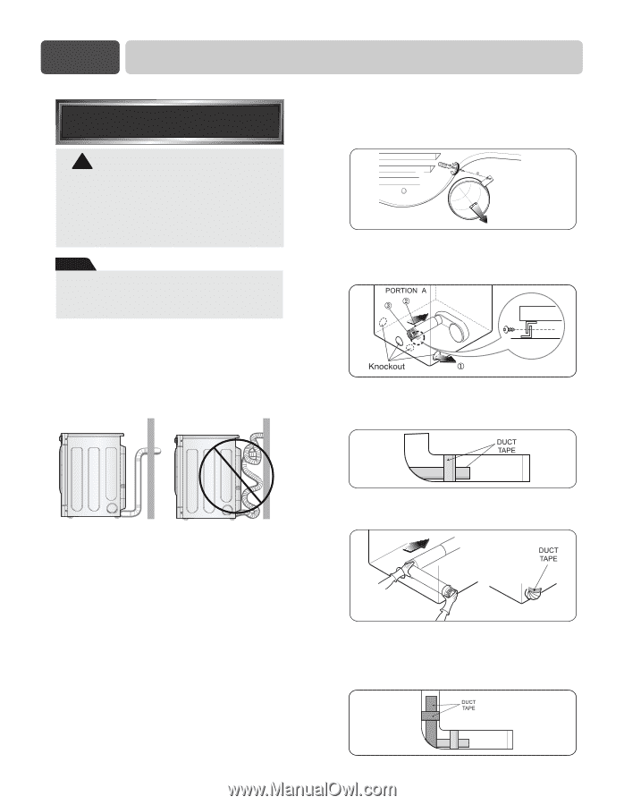
Part 3 INITIAL STEPS FOR INSTALLING YOUR DRYER STEP 3 Connecting the Exhaust and Venting System. ! WARNING! • Use a heavy metal vent. • Do not use plastic or thin foil duct. • Failure to follow these instructions can result in death or fire. • Clean old ducts before installing this dryer. Note The exhaust must be vented to the outside. Improper taping and incorrect installation will cause dryer malfunction. In addition to the following warnings, please refer to manual section on Exhaust Requirements and Maintenance. IMPORTANT: To reduce the risk of fire, combustion, and gas accumulation, the dryer must be vented to the outdoors. Please follow the instructions (and all others in this manual) very carefully. ■ ALTERNATE EXHAUST DIRECTIONS 1. Remove screw and exhaust duct. (Use exhaust kit part #3911EZ9131X.) 2-1. Detach and remove the knockout that matches the desired venting direction (Right side not available on Gas Dryers) 2-2. Connect a short piece of duct to the blower housing and attach the duct to the base. • Do not use plastic or thin foil duct. • Use 4" (10.2 cm) diameter rigid or semi-rigid metal duct (NOTE! Venting materials are not supplied with the dryer, and you should obtain the venting materials necessary for proper installation) • Position the dryer such that the exhaust duct run is as short as possible. • Clean old ducts before installing this dryer • The male end of each section of exhaust duct must point away from the dryer. • Use as few elbow joints as possible. • Use duct tape on all duct joints. • Insulate ductwork that runs through unheated areas in order to reduce condensation and lint build-up on pipe walls. • PLEASE BE AWARE THAT FAILURE TO EXHAUST THE DRYER CORRECTLY WILL VOID THE DRYER'S WARRANTY. 3-1. Insert the male end of a 4" elbow into the female end of a short duct. Tape the joint. 3-2. Insert this assembly elbow first through the hole in the dryer and push the female end of the elbow onto the male end of the blower output shaft. Tape the joint. 11
-
 1
1 -
2
-
3
-
4
-
5
-
6
-
7
-
 8
8 -
 9
9 -
 10
10 -
 11
11 -
 12
12 -
 13
13 -
 14
14 -
 15
15 -
 16
16 -
 17
17 -
 18
18 -
19
-
20
-
21
-
22
-
23
-
24
-
25
-
26
-
27
-
28
-
29
-
30
-
31
-
32
-
33
-
34
-
35
-
36
-
37
-
38
-
39
-
40
-
41
-
42
-
43
-
44
-
45
-
46
-
47
-
48
-
49
-
50
-
51
-
52
-
53
-
54
-
55
-
56
-
57
-
58
-
59
-
60
-
61
-
62
-
63
-
64
-
65
-
66
-
67
-
68
-
69
 |
 |