LG DLG2522W Owners Manual - Page 10
Connecting the Exhaust, and Venting System. - gas dryer
 |
View all LG DLG2522W manuals
Add to My Manuals
Save this manual to your list of manuals |
Page 10 highlights
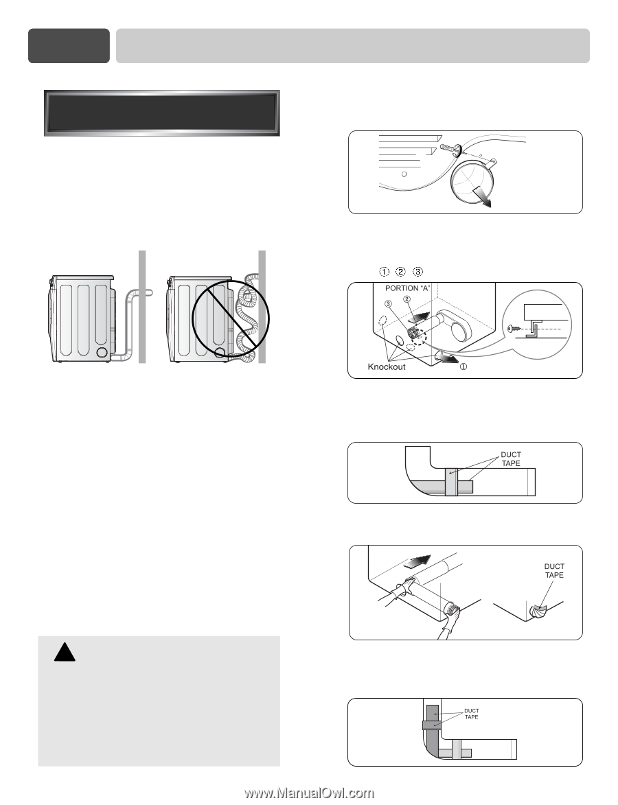
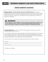
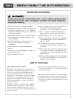
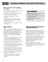
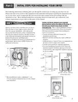
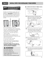
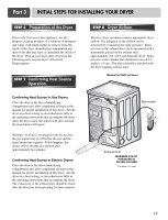
Part 3 INITIAL STEPS FOR INSTALLING YOUR DRYER STEP 3 Connecting the Exhaust and Venting System. In addition to the following warnings, please refer to manual section on Exhaust Requirements and Maintenance. IMPORTANT: To reduce the risk of fire, combustion, and gas accumulation, the dryer must be vented to the outdoors. Please follow the instructions (and all others in this manual) very carefully. I ALTERNATE EXHAUST DIRECTIONS 1. Remove a screw and exhaust duct. 2-1. Detach and remove a knockout at the button, left or right side as desired. (Right Side Vent not available on Gas dryer) , , the order of work. • Do not use thin plastic or foil ducting. • Use 4" (10.2 cm) diameter rigid or flexible metal duct (note: venting materials are not supplied with the dryer, and you should obtain the venting materials necessary for proper installation) • Position the dryer where the exhaust duct is shorter as possible • Clean old ducts before installing this dryer • The male end of each section of exhaust duct must point away from the dryer • Use fewer elbow joints as possible • Use duct tape on all duct joints • Insulate ductwork that runs through unheated areas in order to reduce condensation and lint build-up on pipe walls; and • PLEASE BE AWARE THAT FAILURE TO EXHAUST THE DRYER CORRECTLY WILL VOID THE DRYER'S WARRANTY. ! WARNING! • Use a heavy metal vent. • Do not use a plastic vent. • Do not use a metal foil vent. • Failure to follow these instructions can result in death or fire. • Clean old ducts before installing this dryer 2-2. Reconnect the another duct[11 in(28cm)] to the blower housing, and attach the duct to the base. (Duct is a SVC part) 3-1. Pre-assemble 4" elbow with 4" duct. Wrap duct tape around joint. 3-2. Insert elbow duct assembly first through the side opening and connect the elbow to the internal duct. 9
-
 1
1 -
2
-
3
-
4
-
 5
5 -
 6
6 -
 7
7 -
 8
8 -
 9
9 -
 10
10 -
 11
11 -
 12
12 -
 13
13 -
 14
14 -
 15
15 -
16
-
17
-
18
-
19
-
20
-
21
-
22
-
23
-
24
-
25
-
26
-
27
-
28
-
29
-
30
-
31
-
32
-
33
 |
 |