LG HBLG2350E Service Manual - Page 6
Air Handling Parts
 |
View all LG HBLG2350E manuals
Add to My Manuals
Save this manual to your list of manuals |
Page 6 highlights
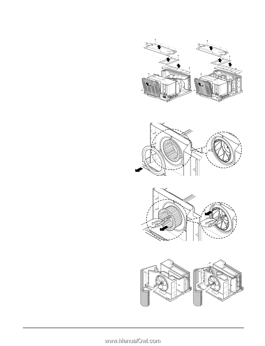
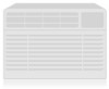
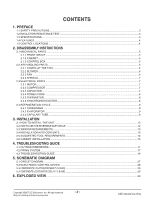
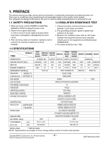
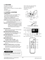
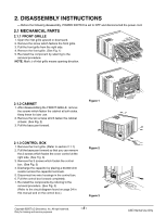
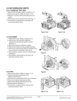
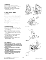
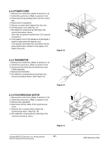
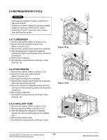
2.2 AIR HANDLING PARTS 2.2.1 COVER (AT THE TOP) 1. Remove the front grille. (Refer to section 2.1.1) 2. Remove the cabinet. (Refer to section 2.1.2) 3. Remove 11 screws which fasten the brace and covers. 4. Remove the covers and the brace. (See Fig. 4) 5. Re-install the components by referring to the removal procedure, above. 2.2.2 BLOWER 1. Remove the cover. (Refer to section 2.2.1) 2. Remove the 3 screws which fasten the evaporator at the left side and the top side. (See Fig. 4) 3. Move the evaporator sideward carefully. 4. Remove the orifice from the air guide carefully. 5. Remove the clamp spring which is clamped to the boss of blower by hand plier. (See Fig. 5) 6. Pull the blower outward, without touching blades. (See Fig. 6) 7. Re-install the components by referring to the removal procedure, above. Figure 4 (a) Figure 5 Figure 4 (b) 2.2.3 FAN 1. Remove the cabinet. (Refer to section 2.1.2) 2. Remove the brace and shroud cover. (Refer to section 2.2.1) 3. Remove the 5 screws which fasten the condenser. 4. Move the condenser sideways carefully. 5. Remove the clamp which secures the fan. 6. Remove the fan. (See Fig. 7) 7. Re-install the components by referring to the removal procedure, above. Figure 6 Figure 7 (a) Copyright ©2007 LG Electronics. Inc. All right reserved. Only for training and service purposes -6- Figure 7 (b) LGE Internal Use Only
-
 1
1 -
 2
2 -
 3
3 -
 4
4 -
 5
5 -
 6
6 -
 7
7 -
 8
8 -
 9
9 -
 10
10 -
 11
11 -
 12
12 -
13
-
14
-
15
-
16
-
17
-
18
-
19
-
20
-
21
-
22
-
23
-
24
-
25
-
26
-
27
-
28
-
29
-
30
-
31
 |
 |