LG HBLG6000R Service Manual - Page 3
Preface - air conditioner
 |
View all LG HBLG6000R manuals
Add to My Manuals
Save this manual to your list of manuals |
Page 3 highlights
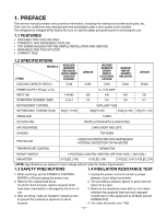
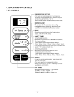
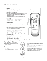
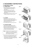
1. PREFACE This service manual provides various service information, including the mechanical and electrical parts, etc. This room air conditioner was manufactured and assembled under a strict quality control system. The refrigerant is charged at the factory. Be sure to read the safety precautions prior to servicing the unit. 1.1 FEATURES • DESIGNED FOR COOLING ONLY • POWERFUL AND INCREDIBLE COOLING • TOP-DOWN CHASSIS FOR THE SIMPLE INSTALLATION AND SERVICE • WASHABLE ONE-TOUCH FILTER • COMPACT SIZE 1.2 SPECIFICATIONS MODELS ITEMS WG5200ER, LW5200ER, HBLG5200E, LWC051JGMK2 KG5200ER ACQ058PL COOLING CAPACITY (BTU/h) 5,200 LW050CE 5,050 WG5200R ACQ052PK M5404R WM5031 LWJ0515PAG LW5200R 5,250 WG6000R M6004R KG6000R HBLG6000R 6,000 LW7000R 76,000 POWER SUPPLY (Phase, V, Hz) 1ø, 115V, 60HZ INPUT (W) 470/480 520 540 620 720 OPERATING CURRENT (AMP.) 4.3/4.4 4.8 5.0 5.8 6.7 REFRIGERANT CONTROL REFRIGERANT CHARGE (R-22) 330g (11.6 Oz) CAPILLARY TUBE 220g(7.8 Oz) 235g (8.3 Oz) 315g (11.1 Oz) INSIDE FAN TURBO OUTSIDE FAN AIR DISCHARGE PROPELLER FAN WITH SLINGER RING 2-WAY (RIGHT AND LEFT) CHASSIS TOP-DOWN PROTECTOR • OVERLOAD PROTECTOR FOR COMPRESSOR • INTERNAL PROTECTOR FOR FAN MOTOR TEMPERATURE CONTROL THERMISTOR ROTARY SWITCH 5 POSITIONS (LOW FAN, HIGH FAN, OFF, HIGH COOL, LOW COOL) FAN MOTOR 6 POLES, 21W 6 POLES, 19W 6 POLES, 21W 6 POLES, 27W • NOTE: Specifications are subject to minor change without notice for further improvement. 1.3 SAFETY PRECAUTIONS 1.4 INSULATION RESISTANCE TEST 1. When servicing, set the POWER of CONTROL BOARD to Off and unplug the power cord. 2. Observe the original lead dress. If a short circuit is found, replace all parts which have been overheated or damaged by the short circuit. 3. After servicing, make an insulation resistance test to prevent the customer's exposure to shock hazards. 1. Unplug the power cord and connect a jumper between 2 pins (black and white). 2. The grounding conductor (green or green and yellow) is to be open. 3. Measure the resistance value with an ohm meter between the jumpered lead and each exposed metallic part on the equipment at all Mode [except POWER OFF]. 4. The value should be over 1 MΩ. -3-
-
 1
1 -
 2
2 -
 3
3 -
 4
4 -
 5
5 -
 6
6 -
 7
7 -
 8
8 -
 9
9 -
10
-
11
-
12
-
13
-
14
-
15
-
16
-
17
-
18
-
19
-
20
-
21
-
22
-
23
-
24
-
25
-
26
-
27
-
28
-
29
-
30
-
31
-
32
-
33
-
34
 |
 |
