LG KU250 Service Manual - Page 2

Table Of Contents - features

Page 2 highlights

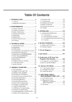
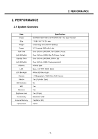
Table Of Contents 1. INTRODUCTION 5 1.1 Purpose 5 1.2 Regulatory Information 5 2. PERFORMANCE 7 2.1 System Overview 7 2.2 Usable environment 8 2.3 Radio Performance 8 2.4 Current Consumption 14 2.5 RSSI BAR 14 2.6 Battery BAR 15 2.7 Sound Pressure Level 16 2.8 Charging 16 3. TECHNICAL BRIEF 17 3.1 General Description 17 3.2 GSM Mode 19 3.3 UMTS Mode 23 3.4 LO generation and distribution circuits...25 3.5 Off-chip RF Components 25 3.6 Digital Baseband(DBB/MSM6245).........34 3.7 Block Diagram(MSM6245 36 3.8 Subsystem(MSM6245 37 3.9 Power Block 45 3.10 External memory interface 50 3.11 H/W Sub System 52 3.12 Main Features 68 4. TROUBLE SHOOTING 73 4.1 RF Component 73 4.2 SIGNAL PATH_UMTS RF 75 4.3 SIGNAL PATH_GSM RF 76 4.4 Checking VC-TCXO Block 77 4.5 Checking Front-End Module Block ........79 4.6 Checking UMTS Block 81 4.7 Checking GSM Block 86 4.8 Checking Bluetooth Block 92 4.9 Power ON Troubleshooting 94 4.10 Charger Troubleshooting 96 4.11 USB Troubleshooting 99 4.12 SIM Detect Troubleshooting 100 4.13 Camera Troubleshooting 102 4.14 Keypad Backlight Troubleshooting ....105 4.15 Main LCD Troubleshooting 106 4.16 Receiver Path 107 4.17 Headset path 109 4.18 Speaker phone path 111 4.19 Main microphone 113 4.20 Headset microphone 115 4.21 Vibrator 117 5. DOWNLOAD 119 5.1 U250/KU250 DOWNLOAD 119 5.1.1 Introduction 119 5.1.2 Downloading Procedure 119 5.1.3 Troubleshooting Download Errors 129 5.1.4 Caution 133 6. BLOCK DIAGRAM 134 6.1 GSM & UMTS RF Block 134 6.2 Interface Diagram 136 7. Circuit Diagram 143 8. pcb layout 147 9. Calibration & RF Auto Test Program (Hot Kimchi 149 9.1 Configuration of HOT KIMCHI 149 9.2 How to use HOT KIMCHI 152 10. Factory Test Mode 154 10.1. Test Program Setting 154 10.2. WCDMA Test Mode 155 10.3. GSM Test Mode 156 11. EXPLODED VIEW & REPLACEMENT PART LIST ..... 157 11.1 EXPLODED VIEW 157 11.2 Replacement Parts

  • 1
  • 2
  • 3
  • 4
  • 5
  • 6
  • 7
  • 8
  • 9
  • 10
  • 11
  • 12
  • 13
  • 14
  • 15
  • 16
  • 17
  • 18
  • 19
  • 20
  • 21
  • 22
  • 23
  • 24
  • 25
  • 26
  • 27
  • 28
  • 29
  • 30
  • 31
  • 32
  • 33
  • 34
  • 35
  • 36
  • 37
  • 38
  • 39
  • 40
  • 41
  • 42
  • 43
  • 44
  • 45
  • 46
  • 47
  • 48
  • 49
  • 50
  • 51
  • 52
  • 53
  • 54
  • 55
  • 56
  • 57
  • 58
  • 59
  • 60
  • 61
  • 62
  • 63
  • 64
  • 65
  • 66
  • 67
  • 68
  • 69
  • 70
  • 71
  • 72
  • 73
  • 74
  • 75
  • 76
  • 77
  • 78
  • 79
  • 80
  • 81
  • 82
  • 83
  • 84
  • 85
  • 86
  • 87
  • 88
  • 89
  • 90
  • 91
  • 92
  • 93
  • 94
  • 95
  • 96
  • 97
  • 98
  • 99
  • 100
  • 101
  • 102
  • 103
  • 104
  • 105
  • 106
  • 107
  • 108
  • 109
  • 110
  • 111
  • 112
  • 113
  • 114
  • 115
  • 116
  • 117
  • 118
  • 119
  • 120
  • 121
  • 122
  • 123
  • 124
  • 125
  • 126
  • 127
  • 128
  • 129
  • 130
  • 131
  • 132
  • 133
  • 134
  • 135
  • 136
  • 137
  • 138
  • 139
  • 140
  • 141
  • 142
  • 143
  • 144
  • 145
  • 146
  • 147
  • 148
  • 149
  • 150
  • 151
  • 152
  • 153
  • 154
  • 155
  • 156
  • 157
  • 158
  • 159
  • 160
  • 161
  • 162
  • 163
  • 164
  • 165
  • 166
  • 167
  • 168
  • 169
  • 170
  • 171
  • 172
  • 173
  • 174
  • 175

- 3 -
1. INTRODUCTION
..............................
5
1.1 Purpose
...................................................
5
1.2 Regulatory Information
............................
5
2. PERFORMANCE
...............................
7
2.1 System Overview
.....................................
7
2.2 Usable environment
.................................
8
2.3 Radio Performance
..................................
8
2.4 Current Consumption
.............................
14
2.5 RSSI BAR
..............................................
14
2.6 Battery BAR
...........................................
15
2.7 Sound Pressure Level
............................
16
2.8 Charging
................................................
16
3. TECHNICAL BRIEF
........................
17
3.1 General Description
...............................
17
3.2 GSM Mode
.............................................
19
3.3 UMTS Mode
...........................................
23
3.4 LO generation and distribution circuits...25
3.5 Off-chip RF Components
.......................
25
3.6 Digital Baseband(DBB/MSM6245)
.........
34
3.7 Block Diagram(MSM6245)
.....................
36
3.8 Subsystem(MSM6245)
..........................
37
3.9 Power Block
...........................................
45
3.10 External memory interface
...................
50
3.11 H/W Sub System
..................................
52
3.12 Main Features
......................................
68
4. TROUBLE SHOOTING
...................
73
4.1 RF Component
.......................................
73
4.2 SIGNAL PATH_UMTS RF
.....................
75
4.3 SIGNAL PATH_GSM RF
.......................
76
4.4 Checking VC-TCXO Block
.....................
77
4.5 Checking Front-End Module Block
........
79
4.6 Checking UMTS Block
...........................
81
4.7 Checking GSM Block
.............................
86
4.8 Checking Bluetooth Block
......................
92
4.9 Power ON Troubleshooting
....................
94
4.10 Charger Troubleshooting
.....................
96
4.11 USB Troubleshooting
...........................
99
4.12 SIM Detect Troubleshooting
..............
100
4.13 Camera Troubleshooting
...................
102
4.14 Keypad Backlight Troubleshooting
....
105
4.15 Main LCD Troubleshooting
................
106
4.16 Receiver Path
....................................
107
4.17 Headset path
......................................
109
4.18 Speaker phone path
...........................
111
4.19 Main microphone
...............................
113
4.20 Headset microphone
..........................
115
4.21 Vibrator
..............................................
117
5. DOWNLOAD
..................................
119
5.1 U250/KU250 DOWNLOAD
..................
119
5.1.1 Introduction
...................................
119
5.1.2 Downloading Procedure
...............
119
5.1.3 Troubleshooting Download Errors 129
5.1.4 Caution
.........................................
133
6. BLOCK DIAGRAM
........................
134
6.1 GSM & UMTS RF Block
.......................
134
6.2 Interface Diagram
................................
136
7. Circuit Diagram
............................
143
8. pcb layout
.....................................
147
9. Calibration & RF Auto Test
Program (Hot Kimchi)
..................
149
9.1 Configuration of HOT KIMCHI
.............
149
9.2 How to use HOT KIMCHI
.....................
152
10. Factory Test Mode
.....................
154
10.1. Test Program Setting
........................
154
10.2. WCDMA Test Mode
..........................
155
10.3. GSM Test Mode
................................
156
11. EXPLODED VIEW &
REPLACEMENT PART LIST
.....
157
11.1 EXPLODED VIEW
............................
157
11.2 Replacement Parts
<Mechanic component>
....................
159
<Main component>
...........................
161
11.3 Accessory
.........................................
174
Table Of Contents