Lacie Spare 12big Rack Network User Manual - Page 8
The Enclosure Core Product
 |
View all Lacie Spare 12big Rack Network manuals
Add to My Manuals
Save this manual to your list of manuals |
Page 8 highlights
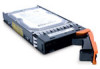
LaCie 12big Rack Network User Manual System Overview page 8 1.2. The Enclosure Core Product The LaCie 12big Rack Network design concept is based on an enclosure subsystem together with a set of plug-in modules and (as supplied) comprises: ✦✦ An Enclosure Chassis comprising: -- A Backplane PCB, -- An Enclosure Management PCB, -- An SAS Expander PCB, to branch from 4 to 12 SAS ports, supporting SATA tunnelling protocol, -- An integral Operator's (Ops) Panel, -- An integral Rear Panel, incorporating an Enclosure ID LED and an NMI push-button (See Fig. 09), and -- A Power Supply Mounting Cage containing two 850W, 100-240V AC auto-ranging, plug-in Power Supply Units, (see Fig. 07), ✦✦ An ATX Server Subsystem, please refer to section 1.4. ATX Server Subsystem for details. ✦✦ A Cooling Cage, containing 10 high speed single rotor axial Fans which are individually pluggable. ✦✦ Up to 12 Drive Carrier modules with 3.5" drives installed, (See Fig. 09). The minimum number of drives which should be installed is 4. NOTE: Dummy Drive Carrier modules must be fitted in all unused drive bays. The High Speed Serial architecture of the LaCie 12big Rack Network storage system provides one 4-channel SAS cable from the SAS Expander PCB to the Motherboard or to the rear mounted SAS Controller/s (if fitted). Module and major component locations are shown in Fig. 02. Fig. 03 - Module Locations
-
 1
1 -
2
-
 3
3 -
 4
4 -
 5
5 -
 6
6 -
 7
7 -
 8
8 -
 9
9 -
 10
10 -
 11
11 -
 12
12 -
 13
13 -
14
-
15
-
16
-
17
-
18
-
19
-
20
-
21
-
22
-
23
-
24
-
25
-
26
-
27
-
28
-
29
-
30
-
31
-
32
-
33
-
34
-
35
-
36
-
37
-
38
-
39
-
40
-
41
-
42
-
43
-
44
-
45
-
46
-
47
-
48
-
49
-
50
-
51
-
52
-
53
-
54
-
55
 |
 |
