Lantronix 22365 Installation Guide Rev C PDF 578.84 KB - Page 10
Magnetic Contact Switch Option
 |
View all Lantronix 22365 manuals
Add to My Manuals
Save this manual to your list of manuals |
Page 10 highlights
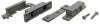
Lantronix EDCA-DIO-01 Install Guide 22365 Magnetic Contact Switch (Option) The optional 22365 Magnetic Contact Switch accessory is sold separately. The 22365 features positive clamping terminals with anti-rotation lugs and captured screws with combination heads for easy, quick installations. The positive terminals do not require washers that can corrode or increase resistance. The captured screws cannot be accidentally removed and lost, and they incorporate heads that will accept both Phillips and flat-blade screwdrivers. 22365 Specifications Voltage Current Power Loop Type (Open or Closed) Electrical Configuration(Normally open or SPDT) Dimensions (WxHxD) Gap Distance (3/4" or 1-1/2" or 2") Housing 100 VAC/VDC max. 0.5 A max. 7.5 W max. Closed Normally open 2.5 x 0.50 x 0.56 in. (64 x 13 x 14 mm) Up to 3/4 in. (See Note 1 below) Flame retardant ABS plastic Note 1: Gap specifications are nominal and may vary ±20%. Gap Specifications are for switch to make. Break distance is approximately 1.1 to 1.5 times make. 22365 Installation Instructions 1. Select desired mounting positions for contact and magnet. Attach with the desired mounting method (e.g., Velcro, industrial tape, nuts and bolts, super glue, rivets, etc.). 2. If protective cover is to be used to shield screw terminals, allow space for "ears" of cover before tightening down mounting screws. Route connecting wires through holes provided in cover. 33790 Rev. C https://www.lantronix.com/ 10
-
 1
1 -
2
-
3
-
4
-
 5
5 -
 6
6 -
 7
7 -
 8
8 -
 9
9 -
 10
10 -
 11
11 -
 12
12
 |
 |
