Lantronix 22365 Installation Guide Rev C PDF 578.84 KB - Page 8
Related Manuals, Troubleshooting
 |
View all Lantronix 22365 manuals
Add to My Manuals
Save this manual to your list of manuals |
Page 8 highlights
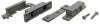
Lantronix EDCA-DIO-01 Install Guide EDCA-DIO-01Install Procedure 1. Mount a mechanical door closure contact switch near the enclosure door so that the opening and closing of the door will trigger the switch. 2. Connect the 12VDC Relay port to the sensor or door contact closure switch. 3. Connect the ALARM Out port to the Digital input port on the Ethernet Switch. 4. Connect to DC Input power last. 5. Verify that the PWR LED is lit. Switch Software Configuration When the EDCA-DIO-01 is installed with a Lantronix managed hardened Ethernet PoE switch, you can set up alarm notifications and clear the logged alarm from either the switch Web UI or the CLI. See the related manual for your particular switch model. Related Manuals • EDCA-DIO-01 Quick Start Guide, 33796 • SISPM1040-582-LRT Install Guide, 33755 • SISPM1040-582-LRT Web User Guide, 33756 • Install Guide, SISPM1040-362-LRT and SISPM1040-384-LRT-C, 33727 • Web User Guide, SISPM1040-362-LRT and SISPM1040-384-LRT-C, 33728 Troubleshooting Follow the steps below to resolve problems. 1. Check the PWR LED. 2. Verify proper EDCA-DIO-01 installation; see the EDCA-DIO-01Install Procedure above. 3. Verify the Installation steps above. 4. Verify connected sensor or alarm and connections. 5. Verify connection with the Lantronix Managed Hardened Ethernet PoE Switch. 6. Record device and site information; see Recording Information below. 7. Contact Lantronix Tech Support. 33790 Rev. C https://www.lantronix.com/ 8
-
 1
1 -
2
-
 3
3 -
 4
4 -
 5
5 -
 6
6 -
 7
7 -
 8
8 -
 9
9 -
 10
10 -
 11
11 -
 12
12
 |
 |
