Lantronix SLP 16 Lantronix SLP - User Guide - Page 11
Safety Precautions
 |
View all Lantronix SLP 16 manuals
Add to My Manuals
Save this manual to your list of manuals |
Page 11 highlights
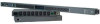
2: Installation Connectors for Optional Figure 2-1. SLP Hardware View Temperature/Humidity Sensor 10/100Base-T Ethernet (RJ45) RS-232 Serial (RJ45) RJ12 Link Outlet Input Current LED Output Power Status LED AC Power Inlet Outlet Connectors for Optional Temperature/Humidity Sensor RS-232 Serial (RJ45) ) AC Power Inlet RJ12 Link Output Power Status LED Input Current LED 10/100Base-T Ethernet (RJ45) Safety Precautions This section contains important safety and regulatory information that should be reviewed before installation. For input and output current ratings, see Power Ratings in Technical Specifications. Only for installation and use in a Service Access Location in accordance with the following installation and use instructions. This equipment is designed to be installed on a dedicated circuit. Dedicated circuit must have circuit breaker or fuse protection. This product has been designed without a master circuit breaker or fuse to avoid becoming a single point of failure. It is the customer's responsibility to provide adequate protection for the dedicated power circuit. Protection of capacity equal to the current rating of the product must be provided and must meet all applicable codes and regulations. In North America, protection must have a 10,000A interrupt capacity. The plug on the power supply cord shall be installed near the equipment and shall be easily accessible. Installation Orientation: SLPVxxxx-02 units are design to be installed in vertical orientation. SecureLinx SLP Remote Power Manager 10
-
 1
1 -
2
-
3
-
4
-
5
-
 6
6 -
 7
7 -
 8
8 -
 9
9 -
 10
10 -
 11
11 -
 12
12 -
 13
13 -
 14
14 -
 15
15 -
 16
16 -
17
-
18
-
19
-
20
-
21
-
22
-
23
-
24
-
25
-
26
-
27
-
28
-
29
-
30
-
31
-
32
-
33
-
34
-
35
-
36
-
37
-
38
-
39
-
40
-
41
-
42
-
43
-
44
-
45
-
46
-
47
-
48
-
49
-
50
-
51
-
52
-
53
-
54
-
55
-
56
-
57
-
58
-
59
-
60
-
61
-
62
-
63
-
64
-
65
-
66
-
67
-
68
-
69
-
70
-
71
-
72
-
73
-
74
-
75
-
76
-
77
-
78
-
79
-
80
-
81
-
82
-
83
-
84
-
85
-
86
-
87
-
88
-
89
-
90
-
91
-
92
-
93
-
94
-
95
-
96
-
97
-
98
-
99
-
100
-
101
-
102
-
103
-
104
-
105
-
106
-
107
-
108
-
109
 |
 |
