Lantronix Spider KVM Over IP Switch User Guide - Page 32
Table 4-3, SpiderDuo Indicator LEDs, SpiderDuo Local KVM, USB
 |
View all Lantronix Spider KVM Over IP Switch manuals
Add to My Manuals
Save this manual to your list of manuals |
Page 32 highlights
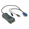
4: Installing the SpiderDuo Device Figure 4-2 SpiderDuo Local KVM, USB, Computer Input and Serial Ports Computer Input Pin# 1 2 3 4 5 6 7 8 Pinouts RS-232 PCU RTS -- -- V TX -- Ground Sense Ground Ground RX -- -- Relay Driver CTS -- Label ID SysOK PCU Color Amber Blue Green Table 4-3 SpiderDuo Indicator LEDs Action On - Unit ID Selected Blinking -Thumb-drive Configuration Successful On - Powered up and OK Blinking - Booting On - Power Unit Connected, AC power is passed through 5. Upon bootup, the terminal window displays the login prompt as shown in Figure 4-4. Figure 4-4 SpiderDuo Login Window 6. To change the default IP auto-configuration settings, type config and press Enter. At the IP configuration prompt, follow the prompts as shown in Figure 4-5. Spider™ and SpiderDuo® KVM-over-IP Device User Guide 32
-
 1
1 -
2
-
3
-
4
-
5
-
6
-
7
-
8
-
9
-
10
-
11
-
12
-
13
-
14
-
15
-
16
-
17
-
18
-
19
-
20
-
21
-
22
-
23
-
24
-
25
-
26
-
 27
27 -
 28
28 -
 29
29 -
 30
30 -
 31
31 -
 32
32 -
 33
33 -
 34
34 -
 35
35 -
 36
36 -
 37
37 -
38
-
39
-
40
-
41
-
42
-
43
-
44
-
45
-
46
-
47
-
48
-
49
-
50
-
51
-
52
-
53
-
54
-
55
-
56
-
57
-
58
-
59
-
60
-
61
-
62
-
63
-
64
-
65
-
66
-
67
-
68
-
69
-
70
-
71
-
72
-
73
-
74
-
75
-
76
-
77
-
78
-
79
-
80
-
81
-
82
-
83
-
84
-
85
-
86
-
87
-
88
-
89
-
90
-
91
-
92
-
93
-
94
-
95
-
96
-
97
-
98
-
99
 |
 |
