Lantronix Spider KVM Lantronix Spider / SpiderDuo - User Guide - Page 34
: Installing the SpiderDuo Device, Package Contents
 |
View all Lantronix Spider KVM manuals
Add to My Manuals
Save this manual to your list of manuals |
Page 34 highlights
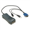
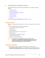
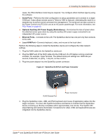
4: Installing the SpiderDuo Device This chapter describes how to install the Lantronix SpiderDuo device. It contains the following sections: Package Contents Installing the SpiderDuo Detector Installation and IP Address Reset Target Computer Setup Client Server Setup Network Environment PCU Power For technical specifications of the SpiderDuo, see Chapter 2: Overview. Package Contents In addition to the SpiderDuo distributed KVM-over-IP module, the package contains the following items: Null modem DB9F to RJ45 serial cable (30.48 mm;120 in) AC Power Cables (1830 ± 30 mm;72 ± 1.2 in) Local KVM cable Computer Input cable Mounting kit (See Appendix D: Mounting Bracket Kit) Quick Start Guide CD-ROM containing documentation and utilities External AC/DC Power Supply Optional power control unit (PCU100-01) Warning: The connectors on the SpiderDuo device are not regular video connectors. To avoid damage to the SpiderDuo device, do not connect cables of any kind other than the cables provided Lantronix. Use the Lantronix power supply only, part number 520-104-R. Installing the SpiderDuo Consider the following factors when planning the installation of the SpiderDuo device. USB Keyboard and Mouse Interfaces-Provide better remote cursor tracking. Some older systems may not support USB devices or there may not be two USB ports available. In these Spider™ and SpiderDuo® KVM-over-IP Device User Guide 34
-
 1
1 -
2
-
3
-
4
-
5
-
6
-
7
-
8
-
9
-
10
-
11
-
12
-
13
-
14
-
15
-
16
-
17
-
18
-
19
-
20
-
21
-
22
-
23
-
24
-
25
-
26
-
27
-
28
-
 29
29 -
 30
30 -
 31
31 -
 32
32 -
 33
33 -
 34
34 -
 35
35 -
 36
36 -
 37
37 -
 38
38 -
 39
39 -
40
-
41
-
42
-
43
-
44
-
45
-
46
-
47
-
48
-
49
-
50
-
51
-
52
-
53
-
54
-
55
-
56
-
57
-
58
-
59
-
60
-
61
-
62
-
63
-
64
-
65
-
66
-
67
-
68
-
69
-
70
-
71
-
72
-
73
-
74
-
75
-
76
-
77
-
78
-
79
-
80
-
81
-
82
-
83
-
84
-
85
-
86
-
87
-
88
-
89
-
90
-
91
-
92
-
93
-
94
-
95
-
96
-
97
-
98
-
99
-
100
-
101
-
102
-
103
-
104
-
105
-
106
-
107
-
108
-
109
-
110
-
111
-
112
-
113
-
114
-
115
-
116
-
117
-
118
-
119
-
120
-
121
-
122
-
123
-
124
-
125
-
126
-
127
-
128
-
129
-
130
-
131
-
132
-
133
 |
 |
