Lantronix XPress-Pro SW XPress-Pro SW - 94000 User Guide - Page 19
Alarms for Power Failure, Power-on Self test POST, The Terminal Block
 |
View all Lantronix XPress-Pro SW manuals
Add to My Manuals
Save this manual to your list of manuals |
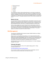
Page 19 highlights
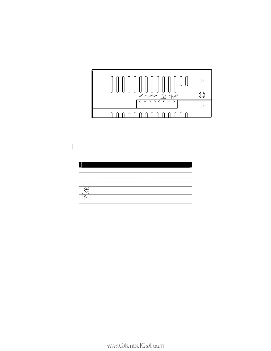
3: Installation 1. Connect the DC power cord to the plug-able terminal block on the Xpress-Pro SW 94000 switch, and then plug it into a standard DC outlet. 2. Disconnect the power cord if you want to shut down the Xpress-Pro SW 94000 switch. Alarms for Power Failure 1. \There are two pins on the terminal block used for power failure detection. It provides the normally closed output when the power source is active. Use this as a dry contact application to send a signal for power failure detection. PWR1 GND PWR2 GND The Terminal Block Power Input 1 (+24VDC) Power Ground Power Input 2 (+24VDC) Power Ground Earth Ground The relay opens if PWR1 or PWR2 fails (1A) Caution: The relay output is normal open position when there is no power to the Xpress-Pro SW 94000 switch. Please do not connect any power source to this terminal to prevent shorting your power supply. Power-on Self test (POST) The Xpress-Pro SW 94000 Switch performs its Power-On Self Test (POST) when the power is switched on. During the POST, the Xpress-Pro SW 94000 switch CPU will: Perform a series of diagnostic procedures to make sure the basic system is functioning properly. A command line prompts when you press the Esc key on a terminal connected to the Xpress-Pro SW 94000 switch serial port during the POST process. Then you can execute the following options: Download runtime software from serial port0 This will download the runtime system image to the Xpress-Pro SW 94000 switch via the serial port. Before selecting this option, make sure: XPress-Pro SW 94000 User Guide 19
-
 1
1 -
2
-
3
-
4
-
5
-
6
-
7
-
8
-
9
-
10
-
11
-
12
-
13
-
 14
14 -
 15
15 -
 16
16 -
 17
17 -
 18
18 -
 19
19 -
 20
20 -
 21
21 -
 22
22 -
 23
23 -
 24
24 -
25
-
26
-
27
-
28
-
29
-
30
-
31
-
32
-
33
-
34
-
35
-
36
-
37
-
38
-
39
-
40
-
41
-
42
-
43
-
44
-
45
-
46
-
47
-
48
-
49
-
50
-
51
-
52
-
53
-
54
-
55
-
56
-
57
-
58
-
59
-
60
-
61
-
62
-
63
-
64
-
65
-
66
-
67
-
68
-
69
-
70
-
71
-
72
-
73
-
74
-
75
-
76
-
77
-
78
-
79
-
80
-
81
-
82
-
83
-
84
-
85
-
86
-
87
-
88
-
89
-
90
-
91
-
92
-
93
-
94
-
95
-
96
-
97
-
98
-
99
-
100
-
101
-
102
-
103
-
104
-
105
-
106
 |
 |